skip to main |
skip to sidebar
Although this looks like a sardine can with wires...it actually is a Bosch electric sunroof motor, from a Porsche 356. Bosch built these in 6 and 12 volt varieties and they all look similar. Bosch DID stamp a voltage identifier on the thin aluminum covers of these little buggers.
Here are all the gubbins of a sunroof motor. I put my digital caliper in the photo to give some idea of the size of the motor. The orange wires in the "U" shaped case are the dual field windings. There are actually TWO windings on each side, which is necessary to make the motor turn both directions. One way to open the sunroof, the other way to close it. The case end piece--to the right of the "U"--has the armature brushes in place. You can see the armature in the center of the photo.
These are just two of eight pages of my own HOW-TO instructions that I made as I did the reconditioning of these motors. I take a dim view of recreating the wheel and these personal instructions make it easy to remember how to do it when I get to the next motor of this type, a week, or six months from now.
I actually had three of these motors to recondition--a six volt and two twelve volt units. This is a late twelve volt motor.
Here are the three victims. Top motor is a six volt unit. Bottom left is an early 12 volt motor [which had burned out field windings] and to the right is a late 12 volt motor. Two are hot to trot to run Porsche sunroofs open and closed, the other is spare parts.
I have reconditioned a TON of Saab 95/96/97 transmissions over the years--this one is number 519--and have seen a lot of different combinations of CRAP oils that owners or mechanics have put in them. This one was new to me and was probably the nastiest GLOP I have ever found. It was about 1/8" thick and was total SLIME, and completely unidentifiable in nature. It looks like RUST but none of the trans parts were rusty. It WAS sticky, so I suspect SOME of the YUK was STP, which is a complete NO NO for these units.
The GOO was all throughout the transmission--thick, ugly, yet more or less pliable, sort of like molasses at zero degrees F. I completely dismantled the transmission and sent the case and covers to my machine shop to be run through the hot tank. No way was I going to spend 2 or 3 hours trying to clean the CRAP out! Clearly the last owner had no clue about what transmission gear oil to use in a Saab transmission.

There is a VERY good reason to use the correct gear oil[s] in a Saab transmission. The exploded view above shows a section of the gears, bearings, etc that fit on the MAIN SHAFT of the Saab 95/96/97 transmission. There are four needle bearings on this shaft--see numbers 30 in the drawing. The numbers 31 indicate a slightly different size needle bearing used inside 4th gear [No. 33] on later transmissions. Gear oils heavier than SAE 75 GL5 or SAE 80 GL5 simply will NOT lubricate these needle bearings. Similarly you must NEVER use a HYPOID differential grease which is available in SAE 90 or SAE 140 viscosity, for the same reason.

Above is a typical differential assembly. Items numbered 6 and 11 are the heavy duty differential carrier bearings. Items 16 and 20 are the pinon shaft bearings. These are large and open, so it is easy for the heavier greases to keep them lubricated. It should be plain to you that this is not the case with the needle bearings in the Saab transmissions. DO use the correct gear oils. I have used AMSOIL synthetic gear oils for 40 years or so and have never had ANY problems with them--they are the kindest thing you can do to your Saab transmission. It is also a very good idea to get off your duff and check the oil level in them about once a month. [I offer a dip stick OR an oil check petcock for this purpose. Either will simplify checking the oil level and make it quicker, easier and less messy than unscrewing the check plug to see if oil will run out on floor].
Here are two of the transmission case pieces--post hot tank--ready for reassembly.
I STILL don't know what that CRAP was in this particular transmission....
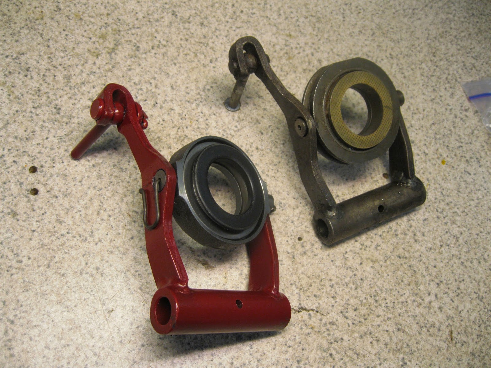
Time to recondition some more clutch release arms. These get worn in the area where the release bearing is held--[see fat arrow at the TOP drawing, above], and in the loop at the outer end and in the clevis pin itself. I weld up the wear areas and machine them back out to fit the new release bearing. NOTE: Currently there are TWO styles of release bearing available, and the mount "pins" on them are different diameters. The release bearings shown in the photo below are the OLD style, with larger diameter pins.
The old release arms are usually pretty grubby when I receive them. Compare an old one [right] to one of my reconditioned arm assemblies [at left]. What you can't see in the photo is how much slop was in all the joints and how bad the release bearing was.
I prefer to recondition a batch of these critters at one time. I did eight of 'em this go-around. If you look carefully you can see early and late release arms. The three on the left [top row] and one on the left [bottom row] are LATE arms. The rest are EARLY arms. There is no difference, functionally. Just a running change that Saab made at some point in the production of these parts, and not at all unusual for a car company.
Once in a while I get to work on my toy, MR T, my 1937 FIAT Topolino. This side view shows the small size of the wee coupe when compared to....
MR Z, our 2012 Honda CRZ Hybrid Coupe. I had installed the heater box [from a 1980 FIAT 124 Spider] but had not installed the control cables or the defroster ducts. So...
I finally convinced myself to press on with that work. Above, you can see the [more or less] rectangular frame for the main switch/relay/fuse panel. Behind that frame are the new defroster ducts. Below the frame is the heater control box.
This photo shows [top left] the end of the heater control box. You can see two of the three control cables coming out of it and two relays [for the left and right semaphores] at the end of the box. The black box to the right is the FIAT heater box.
Here is a straight on view of the heater control box. The defrost ducts [above] are easy to see. Just visible is one of the flasher relays [lower left] and the two semaphore relays [lower right--black].
This car is very small inside and I built it so it all can be UN-bolted. I completely re-wired the car and used plug-in connectors throughout. You can see three of them in this photo. Building a car essentially from scratch is a LOT of work, but it's also a lot of fun. I've enjoyed working on MR T for years. Hell, I might even live long enough to get it finished---HA!
Another of my evils is automotive art in a variety of media. The photo above is a '42 Chevy near the Bandon, Oregon light house. The Oregon lighthouse fancier said the Chevy was her dad's and was one of the last sold before auto production in the USA was stopped because of World War Two. The media? Permanent markers and India ink. Size was 12" x 18".
A Saab enthusiast in Canada owned these four Saabs and the John Deere tractor and fancied Canadian grain elevators. This was done in gouache [opaque water color], markers and India ink. The size of this one was 28" x 40".
A man who likes Willys had me do this one. I used OneShot sign enamel and painted it on galvanized steel. The size was 12" x 16".
I painted this one for me. It was my first car, a '37 Ford slantback. This is a South Dakota setting, showing the windmill on my dad's farm. A reflection of the old farmhouse is in the highly polished side of Henry. Again I used OneShot sign enamel on galvanized steel. Size is 10" x 16".
Another painting using OneShot sign enamel, but this time for fun on one of my aluminum shop cabinet doors. The subject is my '69 Sonett V4 rally car and my first wife, one of the greatest rally navigators known to man. She never got carsick and she never screamed when I got the car sideways at about 80 mph. At night. On a narrow mountain road. Size is 24" x 30".
A 1936 Chevy [and a '40 Ford truck] are the subjects here. The setting is Webster, South Dakota, the building was the family business, lo, those many years ago. Media is gouache, permanent markers, India ink, and at the bottom, pencil. Size is 24" x 30".
I have an extensive automotive library, and of course, these days, there IS Google.... You ever dream about YOUR first car???
I've just reconditioned another Saab V4 engine, this one for a '73 Sonett III. The photo above shows new piston rings about to go onto a cleaned up piston. Note the piston ring expanding tool at the right. The yellow sleeves are to protect the crankshaft when the piston is installed in the engine block. I always have the connecting rod big ends "sized" and always use NEW connecting rod bolts and nuts. These are torqued to a "stretch" or "yield" condition and can NOT be re-used, as they may well break if they are again torqued to yield.

I always take a picture of the installed, new timing gears and tuck the photo into the records for that engine [this one was rebuild number 474...]. Note the new design of the big camshaft gear. Nice quality...BUT...the manufacturer didn't do enough homework. The two standard bolts that retain the intermediate plate [visible at the very bottom of the photo] contacts the outer ring of the aluminum center of the gear. I make special THIN head bolts to retain that plate and use Loctite to keep the bolts in place--no room for lock washers, not even the thin spring plate type. I call that "close, but no banana".

Note the big valves in the right cylinder head. I use these big valves in ALL my reconditioned V4 engines. ALL the valve parts are NEW except the top retaining plates that hold the split keys. The exhaust valves are hardened and I install hardened valve seats for the exhaust valves. This was a warmed up street engine so the owner wished to stay with a single barrel carburetor. I use NEW Weber carburetors on ALL reconditioned V4 engines, this one a 34 ICH.

You can see the Weber carb and special air cleaner assembly, the reconditioned Bosch distributor, the new oil fill cap and the light flywheel and new clutch and pressure plate. What you can't see is the camshaft, reground to Iskenderian F4 specs, and the new tappets [cam followers]. The yellow tabs are shims this clutch set required to get the release bearing plate [the six-sided plate in the center of the pressure plate ass'y] in its correct fore-aft location. The six shims go between the pressure plate and the flywheel. These MUST be offset by installing a slightly thicker shim WASHER under each of the six coil springs inside the pressure plate. About HALF the NEW clutch kits [clutch disc and pressure plate] I get these days require this shimming. I am really picky about the machining of the flywheels to maintain the STOCK depth of the pressure surface to the pressure plate mounting surface, so I know the problem is NOT the flywheels. Necessity, someone said, is the mother of invention......
MR T once again--my '37 FIAT EuroRod. Time--finally--for an exhaust system. In the top photo your can see the tuned header system on the 2-litre FIAT twin cam engine. The white tank to the right is the expansion tank for the aluminum Saab 900 Turbo radiator. The diagonal bar across the engine bay ties the roll cage into the front spring tower. Visible, just ahead of the door is the slot for the right side semaphore, and ahead of that the right vent door for the cabin area.

There is FAR too much STUFF--fuel tank, Panhard rod, suspension trailing arms, and a box on each side behind the seats for A--the electric fuel pump, filter and pressure control, and B--the Optima battery, as well as the standard FIAT 124 rear brake hydraulic pressure control unit--for the exhaust system to run under the car, back of the rear axle. So it must exit the car just ahead of the right rear fender. The photo above shows the system, ready to install under the car. Note the notch in the body of the car [extreme top left in the photo] for pipe clearance.
Tip your head to the right and this photo makes sense. I had to notch one body mount channel piece to clear the pipe at the front, and cut another notch in the body itself at the rear for the pipe back there. The bolt-together flange to the header is on the right.
MR T is now "exhausted." Yup, those are "suicide" doors. The whole hood and front fender assembly tilts forward [see top photo], and the each rear fender comes off after two Allen head bolts are removed and one electrical connector detached. I will add a Coke bottle shaped valence under the door that will disguise the exhaust pipe. The removable roof section, the hood/front fenders ass'y, the rear fenders and the spare tire cover are ALL new fiberglass parts that I laid up, and the lower side valences will also be made of that "wonder" material. [Some folks wonder how they made such a mess using the stuff--HA!]
Here is a FIAT twin cam cylinder head, from a 2-litre [1995cc] carbureted engine. The owner wanted more performance, so in addition to adding a Weber 32/36 DGV-5A carburetor and a set of headers and better exhaust, I put in a set of camshafts from an earlier, 1438cc FIAT twin cam engine. They are an exact interchange, BUT the earlier cams have more lift and will give a big bump in the horsepower curve.
The valves, when pushed open, extend below the level of the cylinder head so a holding jig is necessary to avoid bending one or more valves in the process of doing the camshaft interchange and subsequent valve adjustment. I built this one some years back and it will support several different types of cylinder heads, even a GEO Metro head. [GEO metro....?]
Here are the exhaust camshafts for both engines. Note that the 2-litre cam has big, lazy lobes. You can't see it in the photo but the lift and duration are different between the two camshafts. The cam followers are all in a row at the top of the picture. The actual valve adjustment shims fit in the TOP of each of the followers, not inside.
This shows the exhaust camshaft housing, with the cam and drive gear for the notched belt in place. At this point the housing with the cam followers [not installed here] is ready to be installed on the head.
I build a lot of special tools. The stud with the screwdriver slot in it is one of two. They serve to hold the cam housing-to-head gasket in place and as a guide while I set the cam housing onto the head. All the bolt holes line up--no fudging around. Neat.

Now the fun begins--getting in the correct shims to give proper valve clearance. The tools are FIAT items. Here is how they work: With the camshaft turned so the lobe is angled up, away from the lifter, you use a feeler gauge and measure the clearance [between the camshaft and the follower]. Spec for exhaust valves is 0.018" to 0.021"--I like to set them at 0.020". If you do not have the correct clearance, you push the spade ended black handled gizzmo in between the camshaft and the hardened shim, which is sitting on top of the cam follower "bucket". Then you rotate the little tool [which I have in my hand] around the cam and situate it so its fingers sit on each side of the "bucket". Then you use a shot of compressed air and the shim will pop out of its place on the top of the "bucket".

Measure the thickness of the shim. I use the micrometer to check that my digital caliper is reading accurately today. If the clearance is too tight, you install a thinner shim. Then remove the tool and recheck the clearance. Repeat as required. [Note--spec for the INTAKE valves is 0.015" to 0.019"--I set them at 0.018"].
Note the cam followers ["buckets"] next to the digital caliper. Four of the followers are turned "right side up". Two of them have shims set on them so you can see where the shims fit into the recessed area at the top of the follower.
It is nice to have a full set of shims, separated by thickness sizes.
And here's the finished head, ready to set on the engine. If YOU are doing this, some things to remember: The camshafts MUST be in the correct position, the engine timing mark on the front pulley MUST be on Zero, and you MUST use a NEW timing belt. It is also a really good idea to install a NEW belt tensioner--the bearings in the old one are probably shot. READ THE SERVICE MANUAL!
Contrary to contemporary Germanic myth, even BMW speedometers screw up. GASP! I know that's difficult to believe, but what you see here--on the left in the instrument module--is a dead one. At least, the odometer is dead.
So let's see vas ist kapoot. This is the back of the module. Simple, eh? [That row of lights across the bottom is a sequential warning system tied to increasing speed, to tell a Bimmer pilot how close he/she is to going to jail].
Well yes, simple so far. Remove 8 screws and lift off the plastic outer housing. We're not there yet....
Take out some more screws and whaddaya know? A speedometer! And that little gauge at the base of the tachometer? It is fuel mileage gauge, but in litres per 100 kilometers. See, Bimmer drivers have to have SOMEthing to wow the drivers of LESSOR cars that happen to ride with them [and they explain how it works while speaking German, of course].

This speedometer was built when--apparently--neither BMW or VDO had figured out if they wanted to fish or cut bait. Mechanical operation or electrical? GOSH! I don't know---let's do BOTH. So they did. The speedometer is electric, much like a tachometer. The odometer is driven by a wee electric motor, through a fairly complex gear train.Obviously, they did it because the COULD, not necessarily because it made good sense. So what screws up? Those gears are plastic [of course] and one or more of them get tired of it all and spit off a tooth or two. In this case, TWO gears spit teeth. You can see the dark brown gear [bottom center] that's missing a couple of teeth. Harder to see is a WEE LITTLE shit of a gear just at the bottom of the other brown gear, still in the speedometer apparatus. It's minus a couple of teeth too. The more or less clear plastic housing to the left of the speedo body supports the gear train shafts and keeps the gears in place.

The three new gears are at the lower left. The only fly in the ointment is removing the chewed up WEE gear [that is still on the shaft in this photo]. That shaft is pressed into the wee electric odo drive motor. If you reef on the wee gear to get it off, you'll pull the guts out of the drive motor and that will turn your whole day very dark brown. I used one of my special pullers to remove the little shit. The two new larger gears just drop onto their respective shafts [in the correct order and location--they do not have the same number of teeth]. The new WEE gear has to be carefully pressed onto the motor drive shaft--to the correct depth. Oh yeah, it's great fun repairing something that was a crap design in the first place.
But, here it is--ready to rip once again, and log many happy miles at speeds well above any posted speed limit. Anywhere.
What you see is the familiar Monte Carlo or Saab Deluxe instrument panel. But wait! Take a closer look---this is from a VERY rusty car. In fact the steel instrument panel itself was rusted through in a number of places. I wanted to see what I could salvage from this mess....
The back of the panel didn't look so hot either. Almost all the bolts are rusted beyond any hope of unscrewing. In fact, the clamps for the speedometer and tach have been removed, and the retaining bolts broke off. THAT didn't bode well....
Rust never sleeps, as you can see. At this point I wasn't feeling good about this....
The speedometer case is toast. But...hold on! The "innards" don't look too bad...maybe SOMEthing can be salvaged here, yet....
Well, I'll be...! The innards look better than some I've seen that weren't rusted! The little tool is one [of 50 or more little speedo tools] that I've built. I use this one to operate the speedometer by hand. Turns out I was able to do a normal reconditioning of the speedometer--including replacing the odometer drive gear [which is normal]--and the sucker works like a champ!
My spares stash yielded a good outer housing that cleaned up nicely....
And even the chrome ring and the glass cleaned up just fine. So a word to the wise--don't throw away a Saab speedometer or tachometer just because it has a bit of rust on the outside. It's what's INSIDE that counts! And if you have one you don't want---I DO!


.jpg)