Showing posts with label VINTAGE SAAB. Show all posts

Sunday, June 26, 2016

SAAB MONTE CARLO INSTRUMENT PANEL FOR STANDARD 95/96 CARS

 Most Saab 95 and 96 owners want this instrument cluster in their instrument panel. I include myself in that group of Saab Nuts.... This is the reconditioned instrument set and reconditioned Monte Carlo instrument mount PANEL [see my blog, dated 5 May 16 for that drill...].
 This is a dramatically cleaned up--but not sanded, primed and repainted--standard 95/96 instrument panel. Note that is is for a PRE- 1968 model, because it has the mount area for the inside rear view mirror at the top center of the panel. Remember-- the Saab 95/96 cars up to and including 1967 had SHORTER windshields and rear windows....
 Here is a closer look at the area where the Monte Carlo instrument mount panel will be fitted. Note the rust and discoloration on the main panel. I had not yet cleaned it up, nor repainted it.
 YIKES! A giant HOLE has to be cut to fit the MC panel in place. This has to be done VERY carefully because enough material has to be cut away to clear the instruments, but material must be left for the six mounting studs on the MC panel. I have done this modification before, so I have a pattern that takes the guess work out of the job.
 MUCH very careful trimming must be done to get a good fit of the MC panel. The six warning light holders have to fit onto the back of the MC panel, which usually requires MORE very careful trimming.  Finally, the edges of the stock Saab instrument panel--at the cut-out area--have to be bent to just fit evenly to the MC panel. That MC panel is made of 50 year old plastic, remember, and does NOT care to bend. 
 Saab glove box doors have seven main pieces, as shown. I disassembled  the door, then sanded, primed and painted the four main parts. It was a lot of screwing around, just to get a good looking glove box door, in the correct color.  But there it is....
 This photo shows the flip side of the door. The cup holder part is on the left, the not yet installed Monte Carlo 850 panel on the table, in front...
 ...and here is the glove box door, reassembled, ready to install in the instrument panel.  Looks good, eh?
 OK...Here is the finished product....Cleaned, straightened, sanded, primed, sanded, primed, sanded, primed, then finally given 3 coats of color. Mighty nice, don't you think?
 A closer look at the installed Monte Carlo instrument mount panel, fitted in place, with all the instruments and warning lights.
The final, finishing touch will be a new instrument panel TOP. There are no originals, period. There a VERY few factory replacement top panels around [which were made without the grooves] but good luck finding them. Mark Ashcraft builds an exceptionally nice fiberglass replacement top panel, which comes primed and ready for finish painting and installation. He includes very good How-To instructions.

Thursday, May 5, 2016

SAAB MONTE CARLO INSTRUMENT RECONDITIONING, PLUS

 This is the flip side of a Saab Monte Carlo instrument module, in all its beat up glory. Rust, corrosion, hard handling, and 50 years time have taken their toll.   AK!
 Here is the front of the plastic instrument mounting panel. It was pretty boogered up. You can't see all the cracks and gouges in the panel, in this photo, but they were there.
 The panel had six mounting bolts cast into it--this is the back side--and five of them were ripped out. The panel was also warped and was cracked in about a dozen places. 
 J B Kwikweld to the rescue! A local hardware store was the source for the 4mm x .7mm bolts, as well as the brass pipe I used to provide the centering sleeves for each of the bolts. There were a number of places where I used the JB to straighten the panel by routing out a long groove, laying in the JB, then holding the panel flat as that brand of killer epoxy cured for 24 hours. 
 The front of the panel had eight or ten places where there were a lot of little side by side cracks.  I ground out each tiny crack with a Dremmel tool, then filled it in with auto body filler and sanded it smooth. This sand-fill-sand-fill-sand process went on for a couple of days.... Then it was time to prime-sand-prime for a while, and finally give it three coats of color.  Pretty good, huh?
 Each of the instruments were reconditioned. Here is the full set, ready to install in the car.
And here are the four major instruments sitting in the repaired and repainted mounting panel. All the warning lights--not shown in this photo--were also reconditioned--they were just as grubby as the rest of the module [see photo one--above].  The owner could have just whacked out a panel out of aluminum and screwed it to the instrument panel of his Saab 96, but chose to have me do the job right...and you can see the results. Reminds me of a sign I saw one time on the shop of an old time welder/blacksmith:  "I can mend anything but a broken heart."

Friday, April 24, 2015

SAAB RIBBON SPEEDO MODULE--ELECTRIC TEMP GAUGE

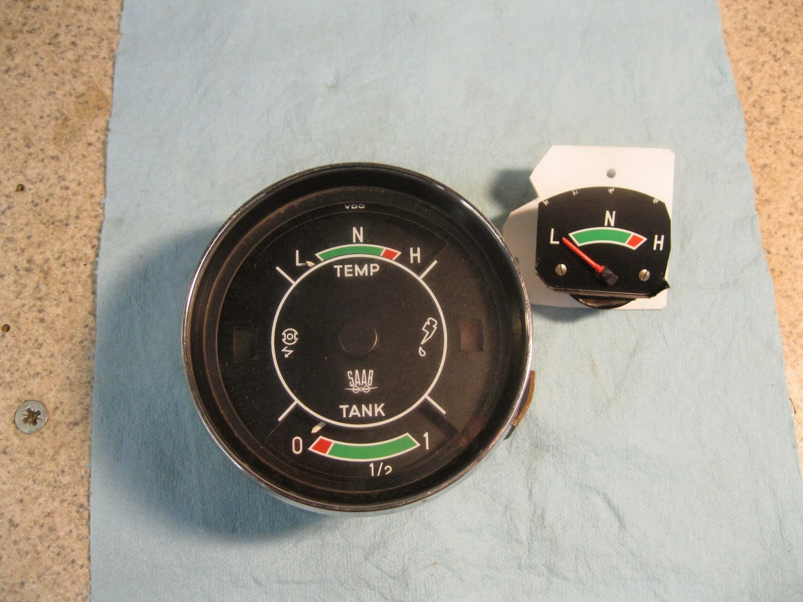
 Here we have two ancient Saab 96 speedometer/multi-gauge units. Because the temperature gauge [left gauge in top module] is a so called "bulb" type, the capillary tube from the sender in the cylinder head to the gauge itself gets damaged and the gauge is kaput. NO new assemblies are available. The SOLUTION is to change to an electric gauge/sender unit combination.  The PROBLEM is figuring out how to mount an electric gauge in the old module. Head scratching time....
 My solution is to remove an electric temperature gauge from a Saab combination gauge unit. I trimmed the gauge face slightly and mounted it on an aluminum plate, as shown above. Making the gauge fit the mount plate and the mount plate fit the speedo module....let's just say that part took the most head scratching.  

Once you get one of these suckers apart, you have quite a few pieces. I've cleaned them all up here, and have repaired the inoperative odometer in this one, and it's ready to go back together. That's another the tricky part, as you might imagine...

 I always have to strip the main, cast aluminum case because it was painted white at the factory and the old white paint flakes off. You can see it is all cleaned and repainted here, and the mechanical bits are all lubricated correctly and yes, the odometer now works!

Go back to the first photo [bottom] to see how the electric gauge looks when it is installed. It is a good "fit" and a good "match" for the other original gauges. This photo shows the back of the module, with the electric gauge mounted. The tan wire is marked "tank", but that's my mistake--I changed it to correctly read "temp sender".
All electric gauges--except an ammeter and a voltmeter--need 3 electrical inputs: 12 volts for reference, an input from the sender unit, and ground. The latter is the black wire in the photo.  So you see, the head scratching worked! 

Thursday, July 3, 2014

SAVING A RUSTY SAAB/VDO SPEEDOMETER

 What you see is the familiar Monte Carlo or Saab Deluxe instrument panel.  But wait! Take a closer look---this is from a VERY rusty car. In fact the steel instrument panel itself was rusted through in a number of places. I wanted to see what I could salvage from this mess....
 The back of the panel didn't look so hot either. Almost all the bolts are rusted beyond any hope of unscrewing. In fact, the clamps for the speedometer and tach have been removed, and the retaining bolts broke off.  THAT didn't bode well....
 Rust never sleeps, as you can see. At this point I wasn't feeling good about this....
 The speedometer case is toast.  But...hold on! The "innards" don't look too bad...maybe SOMEthing can be salvaged here, yet....
 Well, I'll be...! The innards look better than some I've seen that weren't rusted! The little tool is one [of 50 or more little speedo tools] that I've built. I use this one to operate the speedometer by hand. Turns out I was able to do a normal reconditioning of the speedometer--including replacing the odometer drive gear [which is normal]--and the sucker works like a champ!
 My spares stash yielded a good outer housing that cleaned up nicely....
And even the chrome ring and the glass cleaned up just fine. So a word to the wise--don't throw away a Saab speedometer or tachometer just because it has a bit of rust on the outside. It's what's INSIDE that counts! And if you have one you don't want---I DO!

Sunday, August 18, 2013

SAAB SONETT III GLASS HATCH LATCH COVER

 These are NOT fiberglass bolt bins, though they ARE fiberglass. Each, except for the dark one in the center right, is the main body of a cover for a glass hatch latch, for a Saab Sonett III.  The dark one is the steel mould for these things that I built about 25 years ago. The ten bodies shown have been popped out of the mould and trimmed, at this point.
 Here is another view of the ten latch bodies [I believe in mass production, y'see...] and the steel mould. Each latch body has 8 plies of 8 ounce fiberglass cloth. The resin matrix is polyester. You know---that stinky boat resin stuff.
 You can see that I have added a flat fiberglass plate on what will be the TOP surface of each cover. I pre-drilled the holes in the plates before bonding them to the main cover bodies.  The rusty colored "thing" at the bottom is an original, factory plastic latch cover. The sun warps the plastic, makes it brittle and most of them found on Sonett III cars these days are complete junk. 
 Three further stages of assembly are shown here. On the left, the cover with plastic filler completely sanded, ready for paint. In the center, a cover in primer, wet sanded and ready for color. On the right a cover painted and ready for installation in a Sonett III.  There is a whole LOT of hand labor making these things look this good. Sand, fill, sand, fill, swear, sand, swear, fill, swear....
Another view of the last three stages. I supply new stainless steel 1/4-20 bolts and stainless washers with these completed latch covers. These critters won't warp or get brittle--they'll probably outlast the rest of the car. Pretty neat, eh?

Wednesday, April 3, 2013

SAAB SONETT III SHIFTER REBUILD

 The drawing shows the shift linkage for a Sonett III, from the shift tower [on the left] to the transmission [on the right]. Both the shift tower and the linkage support [bolted to the transmission] have two bronze bushings [see arrows]. Saab must have managed a "real deal" on the bushings because they get sloppy after only a few jillion shifts, and that, along with the fact that Saab did not add spring in the linkage to load the shifter to the 3rd-4th gate, can make selecting the correct gear a bit of a crap shoot. 
These are the parts for the linkage at the transmission. But first, one other comment: The actual movement--INSIDE THE TRANSMISSION--from neutral to say, 3rd gear, is only about 1/2 inch [13mm] or so. So it doesn't take much slop in the linkage to confuse gear selection. That's why bushing wear can make things sticky-wicket in the shifting department.

Above--the support fixture with all the bolt holes has a bushing in each end. These are the ones that have to be replaced. Problem is, correct SIZE bushings are not available.
 I get bushings that are just larger than the originals, chuck 'em in the lathe, and carefully machine them until they are just about 0.002" larger outside diameter than the inside diameter of the support housing. Then I press them into the housing. Above is my lathe setup for machining the new bushings.
 Here is a photo of the old bushings and the support housing with the new bushings installed. Note that once I press the new bushings into the housing I still have to ream the INSIDE of each bushing to shaft size plus 0.002".  Note that I also drill and tap the housing for a grease zerk so the bushings can actually be lubricated.  [THAT is a novel idea the Saab engineers never thought of, apparently....]
This is the finished product, ready to go into the car. Might last a few jillion more shifts, especially if it gets a squirt of grease now and again...

Thursday, February 21, 2013

REBUILDING SAAB V4 ENGINE--PART TWO

 Here are the four piston & connecting rod assemblies. The new pistons are 0.031" oversize. At this point all four have been in the engine [without piston rings] so the bearing clearances could be checked with plastigage. The bearing clearances averaged 0.00175". The original connecting rod bolts and nuts have been replaced with new high strength Ford V8 parts. The six small bolts in the photo are not part of the piston/rod assembly.   
 This is by far the best way to install piston rings, using an inexpensive piston ring expander pliers.  You always need to read the instructions that come with the rings. There is usually a peen mark on some of the piston rings that indicates that side of the ring must be installed UP [toward the top of the piston]. I arrange the piston ring end gaps so they are 120 degrees apart when in place on the piston.
 The piston/rod assembly is ready for installation in the engine block. A ring compressor tool is in place, and has compressed the piston rings.  The yellow items on the connecting rods are flexible plastic protectors, to keep guide the rod over the crankshaft journal and prevent the rod bolts from damaging the journal.
 Not a great photo, but it shows the piston being inserted into the block [top left]. I use a small hammer with a wooden handle to tap the piston/rod assembly into place in the block. Note that pistons have a notch in thier crown, indicating that the piston must be installed with the notch pointing to the FRONT of the block.
In this photo, all the rod caps are in place and torqued to 25 ft/lb. I use a bit of Loktite on each of the bolts as a bit of added insurance that a nut will NOT come loose. Note that a new oil pump has been installed [with a NEW oil pump drive shaft] and that the oil pick up strainer is completely clean. I squirt as much engine oil into the new oil pump as it will hold before I bolt it in place. Note the "1.7" on the second crankshaft counterweight from the front, indicating that it is a 1700 crankshaft. At this point, the lower end of the engine is "buttoned up" and ready for the oil pan to be installed.

Wednesday, December 26, 2012

SAAB V4 DISTRIBUTORS--A REVIEW


 This photo shows a wide variety of Bosch distributors and distributor parts--ALL of which were supplied to Saab for their V4 engines. There were at least a dozen DIFFERENT Bosch distributors used on the Saab V4 engine, and while some parts are interchangeable, many are NOT. On the left is a really nasty Bosch/V4 distributor--typical of the way they look when I receive them. Moving to the right, there are 7 different drive gears. To the right of that the MAIN distributor parts---body, main shaft, top shaft. Then, a vacuum control unit [one of a dozen different ones used], a points plate [one of four used], a condensor [one of 10 different ones used], a set of points [one of two used], and a rotor [one of 6 used].The box holds half a dozen different top shafts, then several different movable points plates, and one of two different distributor caps. Finally, there are three different distributor assemblies and two different vacuum control units. I've reconditioned close to 500 Bosch distributors, and I still--occasionally--run onto something I have not seen before!

 Here are two Bosch V4 distributors with MAJOR differences. The top unit is what I call a "notch body" distributor. Note the extended casting on the side, near the top of the distributor body. This requires a vacuum control unit with its mount configured for that notch body. The distributor body below it is a "round body" type. Note that the vacuum control unit is assembled with a round mount.  
 Inside, the fun is just beginning. On the left is a very early internal shaft assembly, on the right one of the later shaft assemblies. Because of the orientation of the rotor notch in the top part relative to the 4 lobes that open the points, these will NOT interchange.  To further the fun, the later assembly [on the right] has four different lobe-to-notch arrangements and they will NOT interchange, either.  In reconditioning these distributors, it is essential to know what parts are compatible. If you don't, you will probably get the thing all back together again and it simply will not work.  Fun stuff, eh?
 This shows the parts of the internal shafts. On the left, starting at the top, the lower shaft. On either side are the two mechanical advance weights, with their control springs just below them. At the bottom, the top shaft, with the four lobes that open the points, and the notch for the rotor.  On the right, the assembled shaft. I control--and can tailor--the mechanical advance curve of the distributor, by changing the advance SPRINGS. I plot the actual curve by running the distributor on the SUN distributor machine, noting the degrees of advance at various readings through the useable RPM range. Sometimes a lot of springs get changed before I'm satisfied with the curve.
Virtually ALL the distributors I receive must have a bushing installed at the bottom of the distributor body. I use a special tool to hold the distributor body so I can drill it in the lathe for the brass bushing. In this picture the bushing has been installed and this setup is for reaming the bushing to the correct inside diameter. This is a fairly delicate process, to get JUST the right I.D. for the shaft, plus just the right clearance. Well....after bushing close to 500 distributors, I DO have that process figured out.
What makes YOUR V4 distributor a candidate for reconditioning? Uneven idle, poor performance, excess fuel consumption, hard starting are a few symptoms. Remember---these gesparkers are 40+ years old! Many Saab V4 owners are amazed at how much better their 40+ year old Saab runs with just a properly reconditioned distributor installed. How's yours running?