Let's ALTERNATE! The photo above shows before and after my reconditioning work.
Though you can't tell unless you look very carefully, it also shows that one alternator
is for a two stroke Saab and one is for a V4, though both have the early cast aluminum fan.
Now look at the FINS on each fan from the back. Note that the fins angle in opposite directions. While both engines turn the same direction [clockwise as viewed from the front], remember that the V4 fan pulley is on the BALANCE SHAFT, so the alternator turns the opposite direction. It is also good to remember that an alternator doesn't give a shit which way it turns---it just produces alternating current [AC]. The "juice"
is then fed through a full wave rectifier whose output is direct current [DC], the stuff the car needs. Cool, huh?
This photo shows all the gubbins. Note that I turned the commutator slip rings on the armature [brass color] down smooth on my lathe. The brush pack is on the extreme left. This alternator is a later unit [tho all are 35 amp, 12 volt] that used the stamped steel fan with the fins angled the correct direction for the Ford/Saab V4.
Here are three alternators that I just reconditioned. Left--late V4. Center--V4, sort of early, with aluminum fan. Note the arrow on the fan, indicating direction of rotation. The alternator on the right is a VERY early V4, also with a cast aluminum fan. So what is the difference between the one in the center and the one on the right?
The difference is in the electrical connections on the back. The one on the left and the one in the center use the 3-connector plug, plus a heavier B+ wire, plus a ground wire. The alternator on the right uses four separate connections, plus ground. All were used on Saabs, in various years, and all are 35 amp, 12 volt alternators.
I actually reconditioned six of the buggers, this session, but these three show the main differences that you might encounter. The most IMPORTANT thing to remember is that an alternator must have the correct fan. The arrow--either cast into the aluminum fan face, or stamped into several of the fins on a stamped steel fan--must indicate a counter-clockwise rotation for a V4. A cast aluminum fan for a two cycle Saab will have the cast-in arrow showing a clockwise rotation. Don't mix 'em up or you'll get to replace a burned-up alternator, and that's no fun...huh?
Showing posts with label SAAB 96. Show all posts
Monday, July 25, 2016
Sunday, June 26, 2016
SAAB MONTE CARLO INSTRUMENT PANEL FOR STANDARD 95/96 CARS
Most Saab 95 and 96 owners want this instrument cluster in their instrument panel. I include myself in that group of Saab Nuts.... This is the reconditioned instrument set and reconditioned Monte Carlo instrument mount PANEL [see my blog, dated 5 May 16 for that drill...].
This is a dramatically cleaned up--but not sanded, primed and repainted--standard 95/96 instrument panel. Note that is is for a PRE- 1968 model, because it has the mount area for the inside rear view mirror at the top center of the panel. Remember-- the Saab 95/96 cars up to and including 1967 had SHORTER windshields and rear windows....
Here is a closer look at the area where the Monte Carlo instrument mount panel will be fitted. Note the rust and discoloration on the main panel. I had not yet cleaned it up, nor repainted it.
YIKES! A giant HOLE has to be cut to fit the MC panel in place. This has to be done VERY carefully because enough material has to be cut away to clear the instruments, but material must be left for the six mounting studs on the MC panel. I have done this modification before, so I have a pattern that takes the guess work out of the job.
MUCH very careful trimming must be done to get a good fit of the MC panel. The six warning light holders have to fit onto the back of the MC panel, which usually requires MORE very careful trimming. Finally, the edges of the stock Saab instrument panel--at the cut-out area--have to be bent to just fit evenly to the MC panel. That MC panel is made of 50 year old plastic, remember, and does NOT care to bend.
Saab glove box doors have seven main pieces, as shown. I disassembled the door, then sanded, primed and painted the four main parts. It was a lot of screwing around, just to get a good looking glove box door, in the correct color. But there it is....
This photo shows the flip side of the door. The cup holder part is on the left, the not yet installed Monte Carlo 850 panel on the table, in front...
...and here is the glove box door, reassembled, ready to install in the instrument panel. Looks good, eh?
OK...Here is the finished product....Cleaned, straightened, sanded, primed, sanded, primed, sanded, primed, then finally given 3 coats of color. Mighty nice, don't you think?
A closer look at the installed Monte Carlo instrument mount panel, fitted in place, with all the instruments and warning lights.
The final, finishing touch will be a new instrument panel TOP. There are no originals, period. There a VERY few factory replacement top panels around [which were made without the grooves] but good luck finding them. Mark Ashcraft builds an exceptionally nice fiberglass replacement top panel, which comes primed and ready for finish painting and installation. He includes very good How-To instructions.
This is a dramatically cleaned up--but not sanded, primed and repainted--standard 95/96 instrument panel. Note that is is for a PRE- 1968 model, because it has the mount area for the inside rear view mirror at the top center of the panel. Remember-- the Saab 95/96 cars up to and including 1967 had SHORTER windshields and rear windows....
Here is a closer look at the area where the Monte Carlo instrument mount panel will be fitted. Note the rust and discoloration on the main panel. I had not yet cleaned it up, nor repainted it.
YIKES! A giant HOLE has to be cut to fit the MC panel in place. This has to be done VERY carefully because enough material has to be cut away to clear the instruments, but material must be left for the six mounting studs on the MC panel. I have done this modification before, so I have a pattern that takes the guess work out of the job.
MUCH very careful trimming must be done to get a good fit of the MC panel. The six warning light holders have to fit onto the back of the MC panel, which usually requires MORE very careful trimming. Finally, the edges of the stock Saab instrument panel--at the cut-out area--have to be bent to just fit evenly to the MC panel. That MC panel is made of 50 year old plastic, remember, and does NOT care to bend.
Saab glove box doors have seven main pieces, as shown. I disassembled the door, then sanded, primed and painted the four main parts. It was a lot of screwing around, just to get a good looking glove box door, in the correct color. But there it is....
This photo shows the flip side of the door. The cup holder part is on the left, the not yet installed Monte Carlo 850 panel on the table, in front...
...and here is the glove box door, reassembled, ready to install in the instrument panel. Looks good, eh?
OK...Here is the finished product....Cleaned, straightened, sanded, primed, sanded, primed, sanded, primed, then finally given 3 coats of color. Mighty nice, don't you think?
A closer look at the installed Monte Carlo instrument mount panel, fitted in place, with all the instruments and warning lights.
The final, finishing touch will be a new instrument panel TOP. There are no originals, period. There a VERY few factory replacement top panels around [which were made without the grooves] but good luck finding them. Mark Ashcraft builds an exceptionally nice fiberglass replacement top panel, which comes primed and ready for finish painting and installation. He includes very good How-To instructions.
Thursday, May 5, 2016
SAAB MONTE CARLO INSTRUMENT RECONDITIONING, PLUS
This is the flip side of a Saab Monte Carlo instrument module, in all its beat up glory. Rust, corrosion, hard handling, and 50 years time have taken their toll. AK!
Here is the front of the plastic instrument mounting panel. It was pretty boogered up. You can't see all the cracks and gouges in the panel, in this photo, but they were there.
The panel had six mounting bolts cast into it--this is the back side--and five of them were ripped out. The panel was also warped and was cracked in about a dozen places.
J B Kwikweld to the rescue! A local hardware store was the source for the 4mm x .7mm bolts, as well as the brass pipe I used to provide the centering sleeves for each of the bolts. There were a number of places where I used the JB to straighten the panel by routing out a long groove, laying in the JB, then holding the panel flat as that brand of killer epoxy cured for 24 hours.
The front of the panel had eight or ten places where there were a lot of little side by side cracks. I ground out each tiny crack with a Dremmel tool, then filled it in with auto body filler and sanded it smooth. This sand-fill-sand-fill-sand process went on for a couple of days.... Then it was time to prime-sand-prime for a while, and finally give it three coats of color. Pretty good, huh?
Each of the instruments were reconditioned. Here is the full set, ready to install in the car.
And here are the four major instruments sitting in the repaired and repainted mounting panel. All the warning lights--not shown in this photo--were also reconditioned--they were just as grubby as the rest of the module [see photo one--above]. The owner could have just whacked out a panel out of aluminum and screwed it to the instrument panel of his Saab 96, but chose to have me do the job right...and you can see the results. Reminds me of a sign I saw one time on the shop of an old time welder/blacksmith: "I can mend anything but a broken heart."
Here is the front of the plastic instrument mounting panel. It was pretty boogered up. You can't see all the cracks and gouges in the panel, in this photo, but they were there.
The panel had six mounting bolts cast into it--this is the back side--and five of them were ripped out. The panel was also warped and was cracked in about a dozen places.
J B Kwikweld to the rescue! A local hardware store was the source for the 4mm x .7mm bolts, as well as the brass pipe I used to provide the centering sleeves for each of the bolts. There were a number of places where I used the JB to straighten the panel by routing out a long groove, laying in the JB, then holding the panel flat as that brand of killer epoxy cured for 24 hours.
The front of the panel had eight or ten places where there were a lot of little side by side cracks. I ground out each tiny crack with a Dremmel tool, then filled it in with auto body filler and sanded it smooth. This sand-fill-sand-fill-sand process went on for a couple of days.... Then it was time to prime-sand-prime for a while, and finally give it three coats of color. Pretty good, huh?
Each of the instruments were reconditioned. Here is the full set, ready to install in the car.
And here are the four major instruments sitting in the repaired and repainted mounting panel. All the warning lights--not shown in this photo--were also reconditioned--they were just as grubby as the rest of the module [see photo one--above]. The owner could have just whacked out a panel out of aluminum and screwed it to the instrument panel of his Saab 96, but chose to have me do the job right...and you can see the results. Reminds me of a sign I saw one time on the shop of an old time welder/blacksmith: "I can mend anything but a broken heart."
Thursday, March 3, 2016
SAAB SPEEDOMETER--DUAL REGISTER INTO A STANDARD 2-STROKE
What we have here is a HYBRID speedometer. My customer wanted a dual register speedometer--as in a Monte Carlo--for use in his standard 1966 96 two stroke car. The trouble was that the Monte Carlo cars--either two-stroke or V4--had a transmission with a 4.88:1 final drive transmission. The '66 two-stroke had a transmission with a 5.43:1 final drive. So the MC speedometer would be WAY WRONG in both SPEED and MILEAGE recording......Hmmmmm.....
Clearly, the solution was to change the internal gearing of the MC speedometer [see first photo]. After some head-scratching, I did that gearing change, and the finished speedometer [above] reads correctly on the test bed, for a Saab with 5.43:1 gears.
Here is the flip side of the finished speedometer. I set the odometer miles to match the miles currently shown on the speedometer in the customer's car. The change-over can be done, but it is nice to prove that the change was done correctly, by running the finished speedometer on the test bed. Good stuff!
Clearly, the solution was to change the internal gearing of the MC speedometer [see first photo]. After some head-scratching, I did that gearing change, and the finished speedometer [above] reads correctly on the test bed, for a Saab with 5.43:1 gears.
Here is the flip side of the finished speedometer. I set the odometer miles to match the miles currently shown on the speedometer in the customer's car. The change-over can be done, but it is nice to prove that the change was done correctly, by running the finished speedometer on the test bed. Good stuff!
Wednesday, January 13, 2016
SAAB 95/96/97 BACK UP LIGHT SWITCHES
These are the [made of unobtainium] back up light switches for Saab 95/96/97 cars that I recondition. The drawing above shows where the switch is located on the Saab transaxle, and the internals of the switch. Nothing much to them...right? Well, yes and no. Because of the nasty environment where they "live", they get really grubby and corroded inside. The trick is to get them apart without destroying them. AH! as the Bard of Avon said, "There's the rub!"
Here are 16 switches. At the bottom, one switch disassembled. Above, are 15 switches that I have reconditioned and tested. As I said, getting them apart without destroying the switch is the trick, and it is a bitch....unless...
...you happen to have my special tools. Top center--the tool that holds the switch so you can use the bottom tool to UN-crimp the steel body of the switch WITHOUT breaking the plastic switch body. The same tool is used to RE-crimp the steel body of the switch. The little red tool is a special holder for trimming tiny brass screws that I sometimes have to use to hold a new connector when one of the electrical connector tabs are broken off.
If you are wondering where to get these tools....they're made of unobtainium, too. Just send me you dead switch and I'll recondition it. When I'm done with it, it will look like one of the 15 switches in the center photo. Good stuff, huh?
Here are 16 switches. At the bottom, one switch disassembled. Above, are 15 switches that I have reconditioned and tested. As I said, getting them apart without destroying the switch is the trick, and it is a bitch....unless...
...you happen to have my special tools. Top center--the tool that holds the switch so you can use the bottom tool to UN-crimp the steel body of the switch WITHOUT breaking the plastic switch body. The same tool is used to RE-crimp the steel body of the switch. The little red tool is a special holder for trimming tiny brass screws that I sometimes have to use to hold a new connector when one of the electrical connector tabs are broken off.
If you are wondering where to get these tools....they're made of unobtainium, too. Just send me you dead switch and I'll recondition it. When I'm done with it, it will look like one of the 15 switches in the center photo. Good stuff, huh?
Sunday, October 18, 2015
SAAB 95 & 96 WIPER MOTORS WIPE AGAIN!
Wiper motors again! This ugly duckling is a Lucas motor for a late SAAB 95 or 96. This one was in its fairly ugly, not working, state when I received it. Nasty....
Here is the same motor...DE-nastified, and ready to be reassembled and tested.
Ah, Henry Ford would be proud of me....three of 'em reconditioned and ready for reassembly.
...and here they are, ready to do their duty happily in a vintage SAAB 95 or 96. All have been tested for both speeds, plus self park. Neat, aye?
Here is the same motor...DE-nastified, and ready to be reassembled and tested.
Ah, Henry Ford would be proud of me....three of 'em reconditioned and ready for reassembly.
...and here they are, ready to do their duty happily in a vintage SAAB 95 or 96. All have been tested for both speeds, plus self park. Neat, aye?
WIPING CLEAN
SAAB/Lucas wiper motor reconditioning time again--three of 'em at a time. Most of 'em look like the one shown above when I take 'em apart---YUK! No wonder they don't work worth a damn. Well...over 40 years of working wiper blades....
Here are three of them--reconditioned. One assembled [on the right], two ready to go together.
Ahh...that's better. The brush plate inside has been replaced on this one--you can see where the wires to the self-park switch and main connector have been spliced.
Here is one of the motors on my test bed. I can test any style Lucas motor with this unit. The electrical connections are exactly the same as if the motor was mounted in a car. No guess work here---I run the motors for a while, on both speeds, and test the self-park feature. Nothing like the right tools for the job--aye?
Here are three of them--reconditioned. One assembled [on the right], two ready to go together.
Ahh...that's better. The brush plate inside has been replaced on this one--you can see where the wires to the self-park switch and main connector have been spliced.
Here is one of the motors on my test bed. I can test any style Lucas motor with this unit. The electrical connections are exactly the same as if the motor was mounted in a car. No guess work here---I run the motors for a while, on both speeds, and test the self-park feature. Nothing like the right tools for the job--aye?
Sunday, June 7, 2015
SAAB V4 DISTRIBUTOR RECONDITIONING
Mass production time again! Here are six [of eight] Bosch distributors for Saab V4 cars, completely disassembled, and with a zillion miles worth of grease and crud cleaned off. They are ready to have the bottom of the distributor housing rebushed. The housing "hogs out" at the bottom, with age and a jillion miles of useage. This wear causes the point gap [thus the dwell and the ignition timing] to fluctuate and the engine runs like crap. Note that the second housing from the right already has a steel bushing installed.
I use a bronze bushing...BUT...first the distributor housing must be reamed to a certain diameter. It is essential that the distributor be held perfectly square and the tool that I made [which is in the lathe chuck in this picture] does that job. You can see that several distributors have been drilled, thus the pile of aluminum FUZZ on the lathe bed.
You can see the bronze bushing set in place, just ready to be pressed into the distributor housing.
Once I get the bushing in place, I have to ream it to the shaft size, plus 0.003". This is a tedious process, but doing the job with a hand reamer makes sure I get the correct fit. Every distributor is a LITTLE DIFFERENT and has different amounts of wear--remember--these suckers are about 50 years old!
You can see the five distributor bodies with bronze bushings and the one with the previously installed steel bushing here. All the shafts have been fitted and they are ready to go back together again. Now the REAL work starts, as the points advance plates must be fitted and adjusted, a vacuum control unit fitted, and then the assembled unit has to go onto the SUN distributor test machine to set the advance curves. This usually means I get to take the suckers apart 2 or 3 times to adjust the mechanical advance gubbins to get the correct advance curve. Swearing usually helps. Quite a lot of swearing helps quite a lot more.
All eight completely reconditioned distributors are shown here. These all have points and a condenser installed. If the customer wants a Pertronix unit, I take out the points and condenser and install the P unit. Then I add a rotor, a cap and a new set of spark plug wires, and the bugger is ready to go into the customer's V4 engine, for another 100,000 miles. Good stuff!
I use a bronze bushing...BUT...first the distributor housing must be reamed to a certain diameter. It is essential that the distributor be held perfectly square and the tool that I made [which is in the lathe chuck in this picture] does that job. You can see that several distributors have been drilled, thus the pile of aluminum FUZZ on the lathe bed.
You can see the bronze bushing set in place, just ready to be pressed into the distributor housing.
Once I get the bushing in place, I have to ream it to the shaft size, plus 0.003". This is a tedious process, but doing the job with a hand reamer makes sure I get the correct fit. Every distributor is a LITTLE DIFFERENT and has different amounts of wear--remember--these suckers are about 50 years old!
You can see the five distributor bodies with bronze bushings and the one with the previously installed steel bushing here. All the shafts have been fitted and they are ready to go back together again. Now the REAL work starts, as the points advance plates must be fitted and adjusted, a vacuum control unit fitted, and then the assembled unit has to go onto the SUN distributor test machine to set the advance curves. This usually means I get to take the suckers apart 2 or 3 times to adjust the mechanical advance gubbins to get the correct advance curve. Swearing usually helps. Quite a lot of swearing helps quite a lot more.
All eight completely reconditioned distributors are shown here. These all have points and a condenser installed. If the customer wants a Pertronix unit, I take out the points and condenser and install the P unit. Then I add a rotor, a cap and a new set of spark plug wires, and the bugger is ready to go into the customer's V4 engine, for another 100,000 miles. Good stuff!
Friday, April 24, 2015
SAAB RIBBON SPEEDO MODULE--ELECTRIC TEMP GAUGE
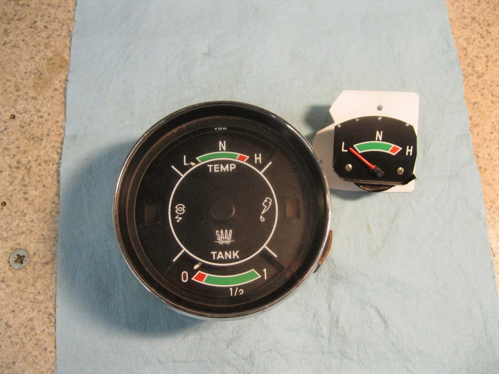
Here we have two ancient Saab 96 speedometer/multi-gauge units. Because the temperature gauge [left gauge in top module] is a so called "bulb" type, the capillary tube from the sender in the cylinder head to the gauge itself gets damaged and the gauge is kaput. NO new assemblies are available. The SOLUTION is to change to an electric gauge/sender unit combination. The PROBLEM is figuring out how to mount an electric gauge in the old module. Head scratching time....
My solution is to remove an electric temperature gauge from a Saab combination gauge unit. I trimmed the gauge face slightly and mounted it on an aluminum plate, as shown above. Making the gauge fit the mount plate and the mount plate fit the speedo module....let's just say that part took the most head scratching.
I always have to strip the main, cast aluminum case because it was painted white at the factory and the old white paint flakes off. You can see it is all cleaned and repainted here, and the mechanical bits are all lubricated correctly and yes, the odometer now works!
Go back to the first photo [bottom] to see how the electric gauge looks when it is installed. It is a good "fit" and a good "match" for the other original gauges. This photo shows the back of the module, with the electric gauge mounted. The tan wire is marked "tank", but that's my mistake--I changed it to correctly read "temp sender".
All electric gauges--except an ammeter and a voltmeter--need 3 electrical inputs: 12 volts for reference, an input from the sender unit, and ground. The latter is the black wire in the photo. So you see, the head scratching worked!
My solution is to remove an electric temperature gauge from a Saab combination gauge unit. I trimmed the gauge face slightly and mounted it on an aluminum plate, as shown above. Making the gauge fit the mount plate and the mount plate fit the speedo module....let's just say that part took the most head scratching.
Once you get one of these suckers apart, you have quite a few pieces. I've cleaned them all up here, and have repaired the inoperative odometer in this one, and it's ready to go back together. That's another the tricky part, as you might imagine...
Go back to the first photo [bottom] to see how the electric gauge looks when it is installed. It is a good "fit" and a good "match" for the other original gauges. This photo shows the back of the module, with the electric gauge mounted. The tan wire is marked "tank", but that's my mistake--I changed it to correctly read "temp sender".
All electric gauges--except an ammeter and a voltmeter--need 3 electrical inputs: 12 volts for reference, an input from the sender unit, and ground. The latter is the black wire in the photo. So you see, the head scratching worked!
Thursday, January 15, 2015
CLOCKS THAT GO "TICK" IN THE NIGHT
A world of square body VDO auto rewind clocks! I have to play the percentages on old clocks, so I usually do four of the buggers at a time. Here they are---all apart, but completely cleaned, oiled and ready for reassembly. At the extreme left center is an auto rewind unit. Below the three outer bodies [silver color] are three clock mechanisms [brass color]. Below them are the white plastic back covers. Whole LOT of pieces!
The red object is one of about 100 special tools I've built to use in the reconditioning of clocks, speedometers, wiper motors, etc. This one is a multi-use HOLDER. The arm of the tool [on the right] fits into my vise, to hold the clock steady while I work on it.
AHA! Four of the buggers reassembled and ready to go. I test them for function and time--on my test bed--before I put the plastic "glass" and the chrome outer ring back on. Remember, these clocks are getting close to being 45 years old, so they "enjoy' a failure rate of about 25%. Old age takes it's toll. These are four that "made it."
The red gizmos behind three of the clocks are in-line fuses. I have to re-solder an internal fusible link, and the 3 amp inline fuse protects the coil that actually makes the reset link arm go "ka-KLIK!" and resets the clock so it keeps on ticking.
The red object is one of about 100 special tools I've built to use in the reconditioning of clocks, speedometers, wiper motors, etc. This one is a multi-use HOLDER. The arm of the tool [on the right] fits into my vise, to hold the clock steady while I work on it.
AHA! Four of the buggers reassembled and ready to go. I test them for function and time--on my test bed--before I put the plastic "glass" and the chrome outer ring back on. Remember, these clocks are getting close to being 45 years old, so they "enjoy' a failure rate of about 25%. Old age takes it's toll. These are four that "made it."
The red gizmos behind three of the clocks are in-line fuses. I have to re-solder an internal fusible link, and the 3 amp inline fuse protects the coil that actually makes the reset link arm go "ka-KLIK!" and resets the clock so it keeps on ticking.
Subscribe to:
Posts (Atom)