Wiper motors again! This ugly duckling is a Lucas motor for a late SAAB 95 or 96. This one was in its fairly ugly, not working, state when I received it. Nasty....
Here is the same motor...DE-nastified, and ready to be reassembled and tested.
Ah, Henry Ford would be proud of me....three of 'em reconditioned and ready for reassembly.
...and here they are, ready to do their duty happily in a vintage SAAB 95 or 96. All have been tested for both speeds, plus self park. Neat, aye?
Sunday, October 18, 2015
SAAB 99 SPEEDOMETER RECONDITIONING
SAAB speedometer reconditioning time again, but this time a SAAB 99 EMS speedo!
These units are full of plastic gears [typical of bean counter work at VDO, I assume] and in the top photo you can see the END of one [of 2] bad plastic gears in this speedo. It is the white gear between the two spiral gears.
The top [main] register has a grey, toothed gear at the right end --it is mostly lead and is pressed onto the register shaft. After umpteen years of work, it loses its grip
--literally--and the odometer stops odometering. I replace that gear--using a number of very special puller and pusher and holder tools--with a gear made of some modern, miracle plastic that is tough and won't slip on the shaft.
This photo shows the bad [cracked and slipping] small, white gear, the main register shaft, and just inside the speedometer frame, the bad [also slipping] part lead drive gear. I replaced both gears, lubed the unit, set the odometer to the figure the customer wanted, then reassembled it and calibrated the speed. Every speedometer has a specific gear ratio. The master VDO book [which I have] shows speeds for the speed needle, given various input speeds [from the speedometer cable]. I use a calibrated input speed, and set the speed needle to agree with the VDO figure for that speedo's gear ratio. No guess work. We all like the speedometer to read right. This one is ready for another 87,000 miles....
These units are full of plastic gears [typical of bean counter work at VDO, I assume] and in the top photo you can see the END of one [of 2] bad plastic gears in this speedo. It is the white gear between the two spiral gears.
This is the speedometer out of the 78 EMS. All looks good here.
--literally--and the odometer stops odometering. I replace that gear--using a number of very special puller and pusher and holder tools--with a gear made of some modern, miracle plastic that is tough and won't slip on the shaft.
This photo shows the bad [cracked and slipping] small, white gear, the main register shaft, and just inside the speedometer frame, the bad [also slipping] part lead drive gear. I replaced both gears, lubed the unit, set the odometer to the figure the customer wanted, then reassembled it and calibrated the speed. Every speedometer has a specific gear ratio. The master VDO book [which I have] shows speeds for the speed needle, given various input speeds [from the speedometer cable]. I use a calibrated input speed, and set the speed needle to agree with the VDO figure for that speedo's gear ratio. No guess work. We all like the speedometer to read right. This one is ready for another 87,000 miles....
WIPING CLEAN
SAAB/Lucas wiper motor reconditioning time again--three of 'em at a time. Most of 'em look like the one shown above when I take 'em apart---YUK! No wonder they don't work worth a damn. Well...over 40 years of working wiper blades....
Here are three of them--reconditioned. One assembled [on the right], two ready to go together.
Ahh...that's better. The brush plate inside has been replaced on this one--you can see where the wires to the self-park switch and main connector have been spliced.
Here is one of the motors on my test bed. I can test any style Lucas motor with this unit. The electrical connections are exactly the same as if the motor was mounted in a car. No guess work here---I run the motors for a while, on both speeds, and test the self-park feature. Nothing like the right tools for the job--aye?
Here are three of them--reconditioned. One assembled [on the right], two ready to go together.
Ahh...that's better. The brush plate inside has been replaced on this one--you can see where the wires to the self-park switch and main connector have been spliced.
Here is one of the motors on my test bed. I can test any style Lucas motor with this unit. The electrical connections are exactly the same as if the motor was mounted in a car. No guess work here---I run the motors for a while, on both speeds, and test the self-park feature. Nothing like the right tools for the job--aye?
Sunday, June 7, 2015
SAAB V4 DISTRIBUTOR RECONDITIONING
Mass production time again! Here are six [of eight] Bosch distributors for Saab V4 cars, completely disassembled, and with a zillion miles worth of grease and crud cleaned off. They are ready to have the bottom of the distributor housing rebushed. The housing "hogs out" at the bottom, with age and a jillion miles of useage. This wear causes the point gap [thus the dwell and the ignition timing] to fluctuate and the engine runs like crap. Note that the second housing from the right already has a steel bushing installed.
I use a bronze bushing...BUT...first the distributor housing must be reamed to a certain diameter. It is essential that the distributor be held perfectly square and the tool that I made [which is in the lathe chuck in this picture] does that job. You can see that several distributors have been drilled, thus the pile of aluminum FUZZ on the lathe bed.
You can see the bronze bushing set in place, just ready to be pressed into the distributor housing.
Once I get the bushing in place, I have to ream it to the shaft size, plus 0.003". This is a tedious process, but doing the job with a hand reamer makes sure I get the correct fit. Every distributor is a LITTLE DIFFERENT and has different amounts of wear--remember--these suckers are about 50 years old!
You can see the five distributor bodies with bronze bushings and the one with the previously installed steel bushing here. All the shafts have been fitted and they are ready to go back together again. Now the REAL work starts, as the points advance plates must be fitted and adjusted, a vacuum control unit fitted, and then the assembled unit has to go onto the SUN distributor test machine to set the advance curves. This usually means I get to take the suckers apart 2 or 3 times to adjust the mechanical advance gubbins to get the correct advance curve. Swearing usually helps. Quite a lot of swearing helps quite a lot more.
All eight completely reconditioned distributors are shown here. These all have points and a condenser installed. If the customer wants a Pertronix unit, I take out the points and condenser and install the P unit. Then I add a rotor, a cap and a new set of spark plug wires, and the bugger is ready to go into the customer's V4 engine, for another 100,000 miles. Good stuff!
I use a bronze bushing...BUT...first the distributor housing must be reamed to a certain diameter. It is essential that the distributor be held perfectly square and the tool that I made [which is in the lathe chuck in this picture] does that job. You can see that several distributors have been drilled, thus the pile of aluminum FUZZ on the lathe bed.
You can see the bronze bushing set in place, just ready to be pressed into the distributor housing.
Once I get the bushing in place, I have to ream it to the shaft size, plus 0.003". This is a tedious process, but doing the job with a hand reamer makes sure I get the correct fit. Every distributor is a LITTLE DIFFERENT and has different amounts of wear--remember--these suckers are about 50 years old!
You can see the five distributor bodies with bronze bushings and the one with the previously installed steel bushing here. All the shafts have been fitted and they are ready to go back together again. Now the REAL work starts, as the points advance plates must be fitted and adjusted, a vacuum control unit fitted, and then the assembled unit has to go onto the SUN distributor test machine to set the advance curves. This usually means I get to take the suckers apart 2 or 3 times to adjust the mechanical advance gubbins to get the correct advance curve. Swearing usually helps. Quite a lot of swearing helps quite a lot more.
All eight completely reconditioned distributors are shown here. These all have points and a condenser installed. If the customer wants a Pertronix unit, I take out the points and condenser and install the P unit. Then I add a rotor, a cap and a new set of spark plug wires, and the bugger is ready to go into the customer's V4 engine, for another 100,000 miles. Good stuff!
Friday, April 24, 2015
SAAB RIBBON SPEEDO MODULE--ELECTRIC TEMP GAUGE
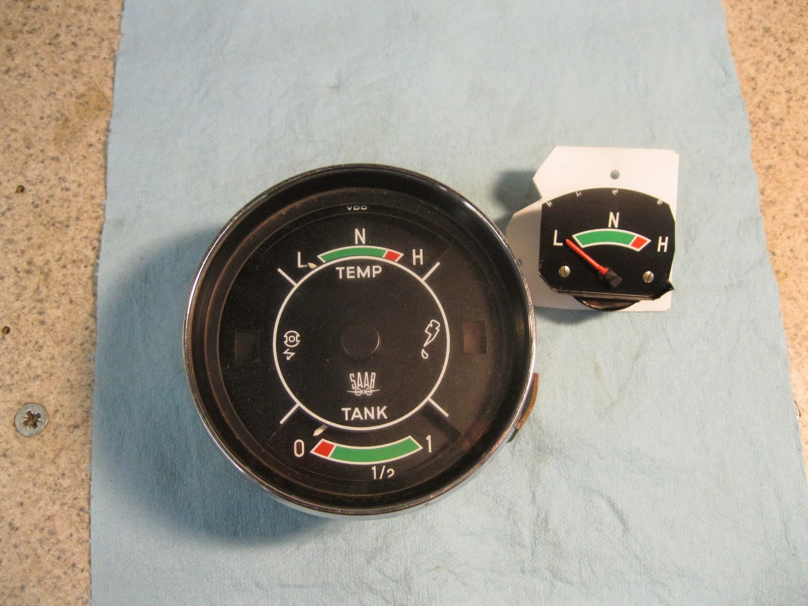
Here we have two ancient Saab 96 speedometer/multi-gauge units. Because the temperature gauge [left gauge in top module] is a so called "bulb" type, the capillary tube from the sender in the cylinder head to the gauge itself gets damaged and the gauge is kaput. NO new assemblies are available. The SOLUTION is to change to an electric gauge/sender unit combination. The PROBLEM is figuring out how to mount an electric gauge in the old module. Head scratching time....
My solution is to remove an electric temperature gauge from a Saab combination gauge unit. I trimmed the gauge face slightly and mounted it on an aluminum plate, as shown above. Making the gauge fit the mount plate and the mount plate fit the speedo module....let's just say that part took the most head scratching.
I always have to strip the main, cast aluminum case because it was painted white at the factory and the old white paint flakes off. You can see it is all cleaned and repainted here, and the mechanical bits are all lubricated correctly and yes, the odometer now works!
Go back to the first photo [bottom] to see how the electric gauge looks when it is installed. It is a good "fit" and a good "match" for the other original gauges. This photo shows the back of the module, with the electric gauge mounted. The tan wire is marked "tank", but that's my mistake--I changed it to correctly read "temp sender".
All electric gauges--except an ammeter and a voltmeter--need 3 electrical inputs: 12 volts for reference, an input from the sender unit, and ground. The latter is the black wire in the photo. So you see, the head scratching worked!
My solution is to remove an electric temperature gauge from a Saab combination gauge unit. I trimmed the gauge face slightly and mounted it on an aluminum plate, as shown above. Making the gauge fit the mount plate and the mount plate fit the speedo module....let's just say that part took the most head scratching.
Once you get one of these suckers apart, you have quite a few pieces. I've cleaned them all up here, and have repaired the inoperative odometer in this one, and it's ready to go back together. That's another the tricky part, as you might imagine...
Go back to the first photo [bottom] to see how the electric gauge looks when it is installed. It is a good "fit" and a good "match" for the other original gauges. This photo shows the back of the module, with the electric gauge mounted. The tan wire is marked "tank", but that's my mistake--I changed it to correctly read "temp sender".
All electric gauges--except an ammeter and a voltmeter--need 3 electrical inputs: 12 volts for reference, an input from the sender unit, and ground. The latter is the black wire in the photo. So you see, the head scratching worked!
Monday, February 2, 2015
SAAB/LUCAS WINDSHIELD WIPER MOTOR RECONDITIONING
Lucas square body wiper motors! For Saabs once again. This is how they look--usually--when I get them....YUK!
All the "innards"... At the top---a motor that hasn't been taken apart yet...Yup, that's how they look when I get the suckers. At bottom right---that's how they look when I'm done with 'em. In the middle---all the "stuff" that goes to make up a wiper motor. Starting at the left: Main housing and drum gear. Round cap below that contains the self park plate. Next on the right is the field winding module, which also carries the brushes. Next is the armature assembly, then the armature housing, and finally the end cap assembly. The sort of triangular "thingie" below the armature is the mount plate, then a worthless sponge dust seal, a washer and the actuating tab. Good stuff!
Here are two reconditioned Lucas/Saab wiper motors. Same, but sightly different. Note the connectors. On the left is the early [1966 Saab 95/96] motor, with two connectors. On the right is the later [1967-69] motor with only one connector. Inside, the motors are identical, and will interchange if you switch connectors...AND...if you hook them up correctly. Some fun!
All the "innards"... At the top---a motor that hasn't been taken apart yet...Yup, that's how they look when I get the suckers. At bottom right---that's how they look when I'm done with 'em. In the middle---all the "stuff" that goes to make up a wiper motor. Starting at the left: Main housing and drum gear. Round cap below that contains the self park plate. Next on the right is the field winding module, which also carries the brushes. Next is the armature assembly, then the armature housing, and finally the end cap assembly. The sort of triangular "thingie" below the armature is the mount plate, then a worthless sponge dust seal, a washer and the actuating tab. Good stuff!
Here are two reconditioned Lucas/Saab wiper motors. Same, but sightly different. Note the connectors. On the left is the early [1966 Saab 95/96] motor, with two connectors. On the right is the later [1967-69] motor with only one connector. Inside, the motors are identical, and will interchange if you switch connectors...AND...if you hook them up correctly. Some fun!
Thursday, January 15, 2015
VOLVO 544 WINDSHIELD WIPER MOTOR REBUILD
VOLVO! This SWF windshield wiper motor came from a Volvo 544. It is single speed, 12 volt unit and is SIMILAR but not quite the same as SWF motors for early Saab and Volkswagen cars. In this photo all the parts have been cleaned and the unit is ready to be lubed with modern, temperature stable, non-hardening lubricant and reassembled. Above the parts are a couple of the page I made as I took the motor assembly apart. I always make drawings and notes like that so the NEXT time I get a motor of that type, I won't have to scratch my head to remember how they work, and how they go together. I'll also know if anyone else has been into that particular motor and left something out.
Bench test time. I like to use a switch just like the one in the car for the test. I run the motors for a few minutes to make sure they run at the correct speed and that the self-park switch works. Next to the battery is another page of drawing and notes on this little SWF motor. This little motor says, "I Roll!"
CLOCKS THAT GO "TICK" IN THE NIGHT
A world of square body VDO auto rewind clocks! I have to play the percentages on old clocks, so I usually do four of the buggers at a time. Here they are---all apart, but completely cleaned, oiled and ready for reassembly. At the extreme left center is an auto rewind unit. Below the three outer bodies [silver color] are three clock mechanisms [brass color]. Below them are the white plastic back covers. Whole LOT of pieces!
The red object is one of about 100 special tools I've built to use in the reconditioning of clocks, speedometers, wiper motors, etc. This one is a multi-use HOLDER. The arm of the tool [on the right] fits into my vise, to hold the clock steady while I work on it.
AHA! Four of the buggers reassembled and ready to go. I test them for function and time--on my test bed--before I put the plastic "glass" and the chrome outer ring back on. Remember, these clocks are getting close to being 45 years old, so they "enjoy' a failure rate of about 25%. Old age takes it's toll. These are four that "made it."
The red gizmos behind three of the clocks are in-line fuses. I have to re-solder an internal fusible link, and the 3 amp inline fuse protects the coil that actually makes the reset link arm go "ka-KLIK!" and resets the clock so it keeps on ticking.
The red object is one of about 100 special tools I've built to use in the reconditioning of clocks, speedometers, wiper motors, etc. This one is a multi-use HOLDER. The arm of the tool [on the right] fits into my vise, to hold the clock steady while I work on it.
AHA! Four of the buggers reassembled and ready to go. I test them for function and time--on my test bed--before I put the plastic "glass" and the chrome outer ring back on. Remember, these clocks are getting close to being 45 years old, so they "enjoy' a failure rate of about 25%. Old age takes it's toll. These are four that "made it."
The red gizmos behind three of the clocks are in-line fuses. I have to re-solder an internal fusible link, and the 3 amp inline fuse protects the coil that actually makes the reset link arm go "ka-KLIK!" and resets the clock so it keeps on ticking.
Saturday, November 29, 2014
PORSCHE SUNROOF MOTOR RECONDITIONING
Although this looks like a sardine can with wires...it actually is a Bosch electric sunroof motor, from a Porsche 356. Bosch built these in 6 and 12 volt varieties and they all look similar. Bosch DID stamp a voltage identifier on the thin aluminum covers of these little buggers.
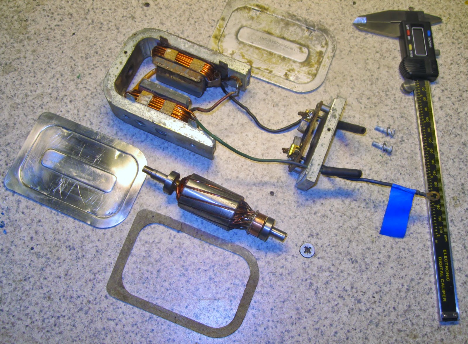
Here are all the gubbins of a sunroof motor. I put my digital caliper in the photo to give some idea of the size of the motor. The orange wires in the "U" shaped case are the dual field windings. There are actually TWO windings on each side, which is necessary to make the motor turn both directions. One way to open the sunroof, the other way to close it. The case end piece--to the right of the "U"--has the armature brushes in place. You can see the armature in the center of the photo.
These are just two of eight pages of my own HOW-TO instructions that I made as I did the reconditioning of these motors. I take a dim view of recreating the wheel and these personal instructions make it easy to remember how to do it when I get to the next motor of this type, a week, or six months from now.
I actually had three of these motors to recondition--a six volt and two twelve volt units. This is a late twelve volt motor.
Here are the three victims. Top motor is a six volt unit. Bottom left is an early 12 volt motor [which had burned out field windings] and to the right is a late 12 volt motor. Two are hot to trot to run Porsche sunroofs open and closed, the other is spare parts.
Here are all the gubbins of a sunroof motor. I put my digital caliper in the photo to give some idea of the size of the motor. The orange wires in the "U" shaped case are the dual field windings. There are actually TWO windings on each side, which is necessary to make the motor turn both directions. One way to open the sunroof, the other way to close it. The case end piece--to the right of the "U"--has the armature brushes in place. You can see the armature in the center of the photo.
These are just two of eight pages of my own HOW-TO instructions that I made as I did the reconditioning of these motors. I take a dim view of recreating the wheel and these personal instructions make it easy to remember how to do it when I get to the next motor of this type, a week, or six months from now.
I actually had three of these motors to recondition--a six volt and two twelve volt units. This is a late twelve volt motor.
Here are the three victims. Top motor is a six volt unit. Bottom left is an early 12 volt motor [which had burned out field windings] and to the right is a late 12 volt motor. Two are hot to trot to run Porsche sunroofs open and closed, the other is spare parts.
Saturday, November 8, 2014
SLIME IN A SAAB V4 TRANSMISSION
I have reconditioned a TON of Saab 95/96/97 transmissions over the years--this one is number 519--and have seen a lot of different combinations of CRAP oils that owners or mechanics have put in them. This one was new to me and was probably the nastiest GLOP I have ever found. It was about 1/8" thick and was total SLIME, and completely unidentifiable in nature. It looks like RUST but none of the trans parts were rusty. It WAS sticky, so I suspect SOME of the YUK was STP, which is a complete NO NO for these units.
The GOO was all throughout the transmission--thick, ugly, yet more or less pliable, sort of like molasses at zero degrees F. I completely dismantled the transmission and sent the case and covers to my machine shop to be run through the hot tank. No way was I going to spend 2 or 3 hours trying to clean the CRAP out! Clearly the last owner had no clue about what transmission gear oil to use in a Saab transmission.
There is a VERY good reason to use the correct gear oil[s] in a Saab transmission. The exploded view above shows a section of the gears, bearings, etc that fit on the MAIN SHAFT of the Saab 95/96/97 transmission. There are four needle bearings on this shaft--see numbers 30 in the drawing. The numbers 31 indicate a slightly different size needle bearing used inside 4th gear [No. 33] on later transmissions. Gear oils heavier than SAE 75 GL5 or SAE 80 GL5 simply will NOT lubricate these needle bearings. Similarly you must NEVER use a HYPOID differential grease which is available in SAE 90 or SAE 140 viscosity, for the same reason.
Above is a typical differential assembly. Items numbered 6 and 11 are the heavy duty differential carrier bearings. Items 16 and 20 are the pinon shaft bearings. These are large and open, so it is easy for the heavier greases to keep them lubricated. It should be plain to you that this is not the case with the needle bearings in the Saab transmissions. DO use the correct gear oils. I have used AMSOIL synthetic gear oils for 40 years or so and have never had ANY problems with them--they are the kindest thing you can do to your Saab transmission. It is also a very good idea to get off your duff and check the oil level in them about once a month. [I offer a dip stick OR an oil check petcock for this purpose. Either will simplify checking the oil level and make it quicker, easier and less messy than unscrewing the check plug to see if oil will run out on floor].
Here are two of the transmission case pieces--post hot tank--ready for reassembly.
I STILL don't know what that CRAP was in this particular transmission....
The GOO was all throughout the transmission--thick, ugly, yet more or less pliable, sort of like molasses at zero degrees F. I completely dismantled the transmission and sent the case and covers to my machine shop to be run through the hot tank. No way was I going to spend 2 or 3 hours trying to clean the CRAP out! Clearly the last owner had no clue about what transmission gear oil to use in a Saab transmission.
There is a VERY good reason to use the correct gear oil[s] in a Saab transmission. The exploded view above shows a section of the gears, bearings, etc that fit on the MAIN SHAFT of the Saab 95/96/97 transmission. There are four needle bearings on this shaft--see numbers 30 in the drawing. The numbers 31 indicate a slightly different size needle bearing used inside 4th gear [No. 33] on later transmissions. Gear oils heavier than SAE 75 GL5 or SAE 80 GL5 simply will NOT lubricate these needle bearings. Similarly you must NEVER use a HYPOID differential grease which is available in SAE 90 or SAE 140 viscosity, for the same reason.
Above is a typical differential assembly. Items numbered 6 and 11 are the heavy duty differential carrier bearings. Items 16 and 20 are the pinon shaft bearings. These are large and open, so it is easy for the heavier greases to keep them lubricated. It should be plain to you that this is not the case with the needle bearings in the Saab transmissions. DO use the correct gear oils. I have used AMSOIL synthetic gear oils for 40 years or so and have never had ANY problems with them--they are the kindest thing you can do to your Saab transmission. It is also a very good idea to get off your duff and check the oil level in them about once a month. [I offer a dip stick OR an oil check petcock for this purpose. Either will simplify checking the oil level and make it quicker, easier and less messy than unscrewing the check plug to see if oil will run out on floor].
Here are two of the transmission case pieces--post hot tank--ready for reassembly.
I STILL don't know what that CRAP was in this particular transmission....
Thursday, October 2, 2014
SAAB CLUTCH RELEASE ARM RECONDITIONING
The old release arms are usually pretty grubby when I receive them. Compare an old one [right] to one of my reconditioned arm assemblies [at left]. What you can't see in the photo is how much slop was in all the joints and how bad the release bearing was.
I prefer to recondition a batch of these critters at one time. I did eight of 'em this go-around. If you look carefully you can see early and late release arms. The three on the left [top row] and one on the left [bottom row] are LATE arms. The rest are EARLY arms. There is no difference, functionally. Just a running change that Saab made at some point in the production of these parts, and not at all unusual for a car company.
Labels:
96 TRANSMISSION,
Saab,
Saab 95,
SAAB 96,
SAAB CLUTCH,
SAAB RELEASE BEARING,
Saab restoration
Friday, September 19, 2014
CONTROLLING MR T'S HEATER
Once in a while I get to work on my toy, MR T, my 1937 FIAT Topolino. This side view shows the small size of the wee coupe when compared to....
MR Z, our 2012 Honda CRZ Hybrid Coupe. I had installed the heater box [from a 1980 FIAT 124 Spider] but had not installed the control cables or the defroster ducts. So...
I finally convinced myself to press on with that work. Above, you can see the [more or less] rectangular frame for the main switch/relay/fuse panel. Behind that frame are the new defroster ducts. Below the frame is the heater control box.
This photo shows [top left] the end of the heater control box. You can see two of the three control cables coming out of it and two relays [for the left and right semaphores] at the end of the box. The black box to the right is the FIAT heater box.
Here is a straight on view of the heater control box. The defrost ducts [above] are easy to see. Just visible is one of the flasher relays [lower left] and the two semaphore relays [lower right--black].
This car is very small inside and I built it so it all can be UN-bolted. I completely re-wired the car and used plug-in connectors throughout. You can see three of them in this photo. Building a car essentially from scratch is a LOT of work, but it's also a lot of fun. I've enjoyed working on MR T for years. Hell, I might even live long enough to get it finished---HA!
MR Z, our 2012 Honda CRZ Hybrid Coupe. I had installed the heater box [from a 1980 FIAT 124 Spider] but had not installed the control cables or the defroster ducts. So...
I finally convinced myself to press on with that work. Above, you can see the [more or less] rectangular frame for the main switch/relay/fuse panel. Behind that frame are the new defroster ducts. Below the frame is the heater control box.
This photo shows [top left] the end of the heater control box. You can see two of the three control cables coming out of it and two relays [for the left and right semaphores] at the end of the box. The black box to the right is the FIAT heater box.
Here is a straight on view of the heater control box. The defrost ducts [above] are easy to see. Just visible is one of the flasher relays [lower left] and the two semaphore relays [lower right--black].
This car is very small inside and I built it so it all can be UN-bolted. I completely re-wired the car and used plug-in connectors throughout. You can see three of them in this photo. Building a car essentially from scratch is a LOT of work, but it's also a lot of fun. I've enjoyed working on MR T for years. Hell, I might even live long enough to get it finished---HA!
Thursday, September 4, 2014
AUTOMOTIVE ART BY ASHCRAFT
Another of my evils is automotive art in a variety of media. The photo above is a '42 Chevy near the Bandon, Oregon light house. The Oregon lighthouse fancier said the Chevy was her dad's and was one of the last sold before auto production in the USA was stopped because of World War Two. The media? Permanent markers and India ink. Size was 12" x 18".
A Saab enthusiast in Canada owned these four Saabs and the John Deere tractor and fancied Canadian grain elevators. This was done in gouache [opaque water color], markers and India ink. The size of this one was 28" x 40".
A man who likes Willys had me do this one. I used OneShot sign enamel and painted it on galvanized steel. The size was 12" x 16".
I painted this one for me. It was my first car, a '37 Ford slantback. This is a South Dakota setting, showing the windmill on my dad's farm. A reflection of the old farmhouse is in the highly polished side of Henry. Again I used OneShot sign enamel on galvanized steel. Size is 10" x 16".
Another painting using OneShot sign enamel, but this time for fun on one of my aluminum shop cabinet doors. The subject is my '69 Sonett V4 rally car and my first wife, one of the greatest rally navigators known to man. She never got carsick and she never screamed when I got the car sideways at about 80 mph. At night. On a narrow mountain road. Size is 24" x 30".
A 1936 Chevy [and a '40 Ford truck] are the subjects here. The setting is Webster, South Dakota, the building was the family business, lo, those many years ago. Media is gouache, permanent markers, India ink, and at the bottom, pencil. Size is 24" x 30".
I have an extensive automotive library, and of course, these days, there IS Google.... You ever dream about YOUR first car???
A Saab enthusiast in Canada owned these four Saabs and the John Deere tractor and fancied Canadian grain elevators. This was done in gouache [opaque water color], markers and India ink. The size of this one was 28" x 40".
A man who likes Willys had me do this one. I used OneShot sign enamel and painted it on galvanized steel. The size was 12" x 16".
I painted this one for me. It was my first car, a '37 Ford slantback. This is a South Dakota setting, showing the windmill on my dad's farm. A reflection of the old farmhouse is in the highly polished side of Henry. Again I used OneShot sign enamel on galvanized steel. Size is 10" x 16".
Another painting using OneShot sign enamel, but this time for fun on one of my aluminum shop cabinet doors. The subject is my '69 Sonett V4 rally car and my first wife, one of the greatest rally navigators known to man. She never got carsick and she never screamed when I got the car sideways at about 80 mph. At night. On a narrow mountain road. Size is 24" x 30".
A 1936 Chevy [and a '40 Ford truck] are the subjects here. The setting is Webster, South Dakota, the building was the family business, lo, those many years ago. Media is gouache, permanent markers, India ink, and at the bottom, pencil. Size is 24" x 30".
I have an extensive automotive library, and of course, these days, there IS Google.... You ever dream about YOUR first car???
Subscribe to:
Posts (Atom)


.jpg)