Saturday, March 23, 2013

SAAB V4 TRANSMISSION TROUBLE

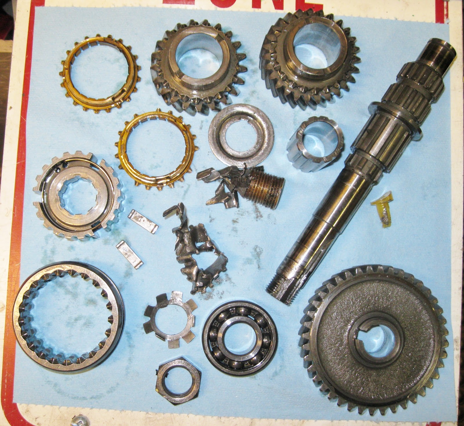
 These are a few of the buggered up transmission parts that I found in the bottom of a transmission I just rebuilt for a customer. This was strange because I usually don't find this sort of damage. It was also strange because the transmission was CLEAN inside. Clearly, someone had been into it recently and had screwed up the job. Also--parts were missing and every case bolt was WAY too tight, as if it had been put together using an impact wrench, which is NOT a good idea. ALL the bolts/nuts in these Saab transaxles must be torqued to the specs provided by Saab in their factory service manual.
 Once I had the bell housing off, it was clear what had happened. The nut at the end of the countershaft [shown] had come loose. The shaft then "floated" and the result was that every part shown--3 gears, the shaft, low and second synchronizer rings, the synchronizer hub and a bunch of smaller parts--were all busted up and had to be replaced.  All because the moron who was into the transmission last did not correctly torque the nut at the end of the countershaft.  OY!
 Well, here is the reassembled gearbox. All countershaft-related damaged parts--as well as others damaged because of the countershaft problem--have been replaced. Note that the 'box is in my factory transmission jig. Using this jig--and the 20-odd factory tools that go with it--is the ONLY way to be sure that an overhaul of one of these transaxles is done correctly.
 There are a number of internal adjustments that MUST be done correctly--some with correct thickness shims, some with feeler gauges, and this one with a dial indicator set up--to insure long life and reliability of the transaxle.
 Here is the finished transaxle. I always specify the use of synthetic transmission oil--AMSOIL being the BEST, in my opinion--so I use an anerobic sealer, which is not attacked by synthetic oils--for all case mating surfaces, and on both sides of the rear cover and top cover gaskets.
Another view of the completed transaxle. Note that there is NO freewheel control lever. This unit has been "neutered" so the freewheel--a carry-over from two-stroke engine days--does not function.  It is very easy for the V4 engine--which actualy has TORQUE [compared to the two stroke] to damage the freewheel unit. It is worth noting that I DO NOT weld internal parts to neuter the freewheel! At any time in the future, the freewheel system COULD--if the owner got soft in the head--be put back into use.

Sunday, March 10, 2013

SAAB V4 CYLINDER HEAD PROBLEMS

 Call it "Murph'y Law" or BumLuck or any other saying regarding mechanical difficulties, but recently I have encountered not one, but TWO problems with V4 Ford/Saab cylinder heads for high performance engines.

Take a look at my exploded view drawing above. Note the exhaust valve hard valve SEAT. Today's unleaded fuel will cause early exhaust valve failure without hardened exhaust valves and valve seats.  So far so good...

I install larger diameter valves and of course larger exhaust valve hard seats. I've rebuilt dozens of V4 engines with these big valve cylinder heads, with no problems. Still, so far so good.

A couple of weeks ago, my machinist found a "pocket"--a casting flaw--in a cylinder head, where he had machined the head to accept a larger diameter hard valve seat.  Result? the head was instant junk. Kauput.

This week, another bad cylinder head....
This head [shown above, before installation] was on an engine installed in a customer's Sonett III, and I discovered--during the 500 mile drive-off--that the right side exhaust pipe was putting out WHITE smoke. Not a lot at first, but it got worse as the end of the 500 miles approached, it was obvious that it was not going to get better. A compression check showed equal compression in all four cylinders and a vacuum gauge check showed steady--and correct--manifold vacuum for this elevation [1350 feet above sea level].

I retorque the cylinder heads and intake manifold to factory spec's 3 times during the 500 mile drive-off runs. The drive-off period allow correction of [usually] small glitches that always appear--in any number of areas--when a car has undergone a full restoration.

I removed the carburetor, intake manifold and right hand cylinder head. Close examination of the head and intake manifold gaskets showed no damage to either, but it was clear that there was a big problem in the forward [No. 1] combustion chamber. The exhaust valve was VERY white, indicating a lot of heat, and there was a bit of fluid around the intake valve. I had certainly found the area of the problem.

NOTE: White smoke in the exhaust means coolant is being sucked into the combustion chamber. Blue smoke means OIL is being sucked into the combustion chamber, either past the valve guides or past the piston rings, or both.  Black smoke means the engine carburetion is WAY too RICH.  Smoke of ANY kind from the exhaust means further investigation is needed, and soon.

The reason for the problem was a crack in the cylinder head at the intake valve seat, where apparently the machining of the head to accept a larger valve had either come close to another pocket in the head casting, or was simply because after machining, the wall thickness between the seat area and the water jacket was thin enough that it cracked with the heat of  combustion.  NOTE: both head were magnefluxed after machining and showed NO cracks.   

Well...shit happens. Particularly when you are trying to get a quart's worth of work out of, essentially, a pint pot. My modified V4 engines produce 115 to 140 horsepower, depending on how thick the customer's wallet is, but the more power you produce
the more possible are the unexpected results. Usually....everything is just fine and the customer gets a really nice engine that will be as reliable as a factory engine.

But sometimes...shit happens.  That's why we ALWAYS do a 500 mile drive-off before we deliver a restored Saab to it's owner, and why we insist that the owner of one of our reconditioned V4 engines follow the instructions we include with the engine when we ship it to him. 

Saturday, March 2, 2013

SAAB V4 ENGINE REBUILD--PART 4

 First--my apologies for less than wonderful photos. A BLACK engine is not the greatest for award-winning photography...This is the completed Ford/Saab V4 high performance engine, ready to go to the owner, to "wake up" a Saab 96. It will produce 110-115 horsepower--quite a step up from the original 73...
The car in the background is my '37 FIAT Topolino, "MR T".
 Front view. Note the timing cover--modified to give room for a radiator with electric fans. Behind the cover are special timing gears--steel gears for crankshaft and balance shaft, aluminum gear for the camshaft. The cam itself is a regrind to Iskenderian F4 specs. Atop the engine is a Weber 32/36 DGV-5A carburetor and air cleaner.
Right front corner.  The new oil filter and water pump are visible. Not visible--big valve cylinder heads and fully balanced crankshaft and associated parts.  I reconditioned and lightened the rocker arms as well. Note the engine lift [in red], an item I built 40+ years ago.  Good tools last a very long time...
Arse end. Note the reconditioned distributor and high performance Magnecore plug wires. Note also the light flywheel and matched pressure plate. The blue paint indicates the balance-match [pressure plate to flywheel] point. The bits of green tape seen here and there are to cover coolant pipes, etc, as the engine is to be shipped to it's owner in another state. I send along a compete listing of all the parts and all the work done on these engines [9 pages long on this one...] plus a short "manual" on doing the necessary re-torques and adjustments as the engine is driven in the owner's car.

Friday, February 22, 2013

SAAV V4 ENGINE REBUILD--PART 3

 This is a lightened flywheel on the V4 engine. Note that quite a lot of material has been removed around the OUTER part of the flywheel. I used NEW flywheel bolts because these bolts are torqued to 50 ft/lb, which is a "stretch" or "yeild" condition that Ford specified. No locking washers are used. Note the yellow paint between two of the bolt heads. This shows the mounting location for the flywheel, on the crankshaft, since this is a fully balanced engine. The balancer also put peen marks at this point. I add the paint so the next "wrench" who gets into this engine may notice that the engine has been balanced, and will, hopefully, reinstall the flywheel at that same location on the crankshaft.
 I use a transmission clutch [input] shaft to center the clutch disc in the flywheel. I also use a witches' brew to put a thin coat of lubricant into the pilot bushing.  My brew is 60% AMSOIL 75/90 transmission oil, 15% STP, and 25% molybdenum disulfide assembly lube. Mixed thoroughly.
 The pressure plate is balanced to the flywheel. The paint--and peen marks--show the correct location for the pressure plate mounting on the flywheel. It is good to know that the release bearing pressure surface of the pressure plate--the flat plate where the inpu

Thursday, February 21, 2013

REBUILDING SAAB V4 ENGINE--PART TWO

 Here are the four piston & connecting rod assemblies. The new pistons are 0.031" oversize. At this point all four have been in the engine [without piston rings] so the bearing clearances could be checked with plastigage. The bearing clearances averaged 0.00175". The original connecting rod bolts and nuts have been replaced with new high strength Ford V8 parts. The six small bolts in the photo are not part of the piston/rod assembly.   
 This is by far the best way to install piston rings, using an inexpensive piston ring expander pliers.  You always need to read the instructions that come with the rings. There is usually a peen mark on some of the piston rings that indicates that side of the ring must be installed UP [toward the top of the piston]. I arrange the piston ring end gaps so they are 120 degrees apart when in place on the piston.
 The piston/rod assembly is ready for installation in the engine block. A ring compressor tool is in place, and has compressed the piston rings.  The yellow items on the connecting rods are flexible plastic protectors, to keep guide the rod over the crankshaft journal and prevent the rod bolts from damaging the journal.
 Not a great photo, but it shows the piston being inserted into the block [top left]. I use a small hammer with a wooden handle to tap the piston/rod assembly into place in the block. Note that pistons have a notch in thier crown, indicating that the piston must be installed with the notch pointing to the FRONT of the block.
In this photo, all the rod caps are in place and torqued to 25 ft/lb. I use a bit of Loktite on each of the bolts as a bit of added insurance that a nut will NOT come loose. Note that a new oil pump has been installed [with a NEW oil pump drive shaft] and that the oil pick up strainer is completely clean. I squirt as much engine oil into the new oil pump as it will hold before I bolt it in place. Note the "1.7" on the second crankshaft counterweight from the front, indicating that it is a 1700 crankshaft. At this point, the lower end of the engine is "buttoned up" and ready for the oil pan to be installed.

Wednesday, February 20, 2013

SAAB V4 ENGINE REBUILD---PART 1

 You are looking down into the block of an overbored 1.7 litre Ford/Saab V4 engine that I'm rebuilding in my shop. You can see new balance shaft bearings, a new steel timing gear, and the fully balanced crankshaft. You can't see it because of its small size, but "BB3415" is stamped into the crankshaft. That indicates that the balance shop--Bert Beck Custom Engines--has recorded this crankshaft as the 3415th crankshaft they have balanced over the years. By now, they know what they're about! 
 These are the main bearing caps and their retaining bolts. All the parts have been meticulously cleaned. New main bearings are installed and the clearances checked with Plastigage. Average bearing clearances are 0.00175"---I make a "map" of all engine clearances a part of my records, and give the customer a copy as well.
The main bearing caps are installed and torqued to factory spec [72 ft/lb]. You can't see it here, but I install the rear main bearing seal as I install the rear cap. That assures a proper "fit" of the seal, with no chance of damaging the seal when it is fitted.  You can see from the photos that the engine is VERY clean. That's the way I want it when I rebuild an engine.

Wednesday, February 6, 2013

MY FIAT TOPOLINO HEATER SYSTEM

 These three  critters are parts to make demisting/defrosting possible in MR T, my '37 FIAT "EuroRod". Top pair are the air outlet nozzles at the base of the windshield. Bottom is the fitting that slips into the stock Fiat 124 Spider heater box.
 This is the heater box, mounted inside the cabin. At the extreme top is the defrost air fixture, fitted into the heater box.
 This photo, taken from outside the car looking down through the [not yet installed] windshield, shows the two defroster delivery nozzles bolted in, at the base of the windshield.  The orange knobs cover the windshield wiper arm actuators. The wiper motor and linkage are stock Fiat 124 Spider, narrowed slightly.
The drawing shows the whole heater/defroster system. Outside air comes into the system when the cowl door on the right side of the car is opened [extreme lower right]. Just inboard is a second door, which lets an adjustable amount of fresh air in on the passenger's legs. If the outside door is closed, this door [when open] lets air inside the cabin to recirculate through the heater.
Air is directed to the top of the stock heater box, where it passes over the heater core and either out the bottom, into the cabin, or up to the defroster tubes, or both, depending upon the position of the slide controls on the front of the heater control panel.
A bit of fabrication was required, but that's part of the fun. I was determined to have an effective heater/defroster system in this little mouse, so there it is.

Tuesday, January 29, 2013

BMW Switch Reconditioning

 Back to bikes!  This is the BMW headlamp pod with the reconditioned combination speedometer/tachometer unit that you saw in an earlier blog. This concerns reconditioning the handlebar switches, seen on the left and right in the photo above.
 Here is a close-up of the headlamp assembly with the combination gauge and the right switch. Of the switches, the one on the left switches on the stop lamp when the front brake is applied. The right switch controls the left/right direction signals and engine start.
 This is a close-up of the two switches for the right handlebar.
The drawing shows the component parts of the LEFT handlebar switch which controls high & low headlight beams and the horn. As the rider moves the thumb control the rotating contact plate decides which beam is "ON". When the button is pushed "IN", the horn sounds. Quite a lot of "stuff" in a very small switch body.

Other than a broken wire, the only thing wrong with this switch was 40+ years of built up corrosion between the brass parts. After I cleaned it all up and repaired the broken wire...VOILA!  Good for another 40 years! 

Sunday, January 20, 2013

Subaru, Saab and Great Designers

 Meet "Mr. B", my '87 Subaru Brat 2-4 wheel drive pickup. The other day the muffler [located just behind the rear axle] decided it was tired and got REAL loud. I replaced the rear section of pipe and the muffler and while I was at it, added a Monza dual outlet pipe tip. Hot ziggety!
 There you see the exhaust tip in all its exhausting glory. So what's the big deal, here, and what's the connection with Saab, you ask?  And what is this "Great Designer" business, anyhow?  The Subaru connection to Saab was Saab's 9-2, the badge engineered Subaru WRX wagon that Saab sold for a year or so. An excellent car, but not one the Saab snobs liked because it wasn't built in Trollhattan. Now for the designer part.
The Brat was designed by Alex Sarantos Tremulis, who also designed the '48 Tucker, added the chrome front fender exhaust pipes on the supercharged Cord, designed the '40 Chrysler Thunderbolt, a number of Ford show cars, and the world's fastest motorcycle, the streamlined, Triumph powered Gyronaut [ 245.667 mph at Bonneville] and managed to get a full sized motor home to 97.6 mph on Muroc dry lake in Southern California.

I was privileged to meet Alex several times at Art Center College of Design when I was an instructor there. He never stopped thinking, dreaming and designing and his knowledge of aerodynamics was amazing. At that time he owned three Tuckers and always drove one when he visited our school.

I've owned several "designer cars" but Mr. B is probably the coolest of all of 'em. 

SAAB Distributor Test Machine

 As promised, here is the SUN distributor test machine, with a Bosch/Saab V4 distributor installed for testing. When the machine is running, an arrow appears on the large black INNER ring below the distributor. Just outboard of that is another black ring with degrees etched into its surface. As distributor RPM increases [by turning the knob at the bottom, below the black rings] the arrow moves anti-clockwise, indicating degrees of advance for that RPM. The top meter on the right measures the RPM. I plot the RPM for each degree of advance, in order to see the mechanical advance curve.  
A typical advance curve--taken right from my distributor reconditioning records book--is shown in RED above, plotted over a set of minimum/maximum curves, as shown for that particular distributor, in the Saab V4 Service Manual.

When the actual plotted curve [RED] is NOT within the factory spec's, I have to disassemble the distributor and change one [or both] of the wee springs in the advance mechanism. Depending upon the distributor type, there may or may not be an additional mechanical adjustment that I can make.  Remember---there are at least a dozen different Bosch distributors used by Saab in their V4 model run from 1967 to 1980.
Without plotting the mechanical advance curve, using the SUN machine, you have no idea what the distributor is doing and I guarantee you--if the curve is significantly outside the minimum/maximums, the engine will run poorly, no matter what tune-up and/or repair you have done to it.

The bottom curve is a plot of the vacuum advance, also done on the SUN machine, or with a special machine I built for the purpose. Again, Saab shows the ideal minimum/maximums for that curve. The RED plot shows the curve of the vacuum advance unit I used for this particular recondition job.  One thing to note:  if the vacuum advance does not work, the engine will run like crap even if you have the timing and carburetion set perfectly.  How is YOUR V4 engine running?

One thing I have found out over the years of reconditioning distributors---the SUN machine never lies.    

Tuesday, January 15, 2013

DISTRIBUTOR RECONDITIONING

 It all comes together! Above--seven reconditioned Saab V4 Bosch distributors. In the center, the last one, still in one of my holding fixtures. Each distributor has been re-bushed, and all new parts installed, including the vacuum control units.
Here are the seven reconditioned distributors. Depending upon the customer's needs, they may be delivered with points and condenser installed, or a solid state Pertronix unit, if that's what the customer wants. All will have a new rotor and new distributor cap.  If the customer wants a new spark plug wire set, he/she can get that too.  
Next step--I'll put each one on the SUN distributor machine and set the mechanical advance curve. The vacuum advance curves have already been plotted on the tech sheet for that distributor. I give the customer a copy of the tech sheet, which shows the advance curves and all the parts that were used for the rebuild.

The next blog--the mysteries of the SUN machine...heh heh heh.....

Wednesday, December 26, 2012

SAAB V4 DISTRIBUTORS--A REVIEW


 This photo shows a wide variety of Bosch distributors and distributor parts--ALL of which were supplied to Saab for their V4 engines. There were at least a dozen DIFFERENT Bosch distributors used on the Saab V4 engine, and while some parts are interchangeable, many are NOT. On the left is a really nasty Bosch/V4 distributor--typical of the way they look when I receive them. Moving to the right, there are 7 different drive gears. To the right of that the MAIN distributor parts---body, main shaft, top shaft. Then, a vacuum control unit [one of a dozen different ones used], a points plate [one of four used], a condensor [one of 10 different ones used], a set of points [one of two used], and a rotor [one of 6 used].The box holds half a dozen different top shafts, then several different movable points plates, and one of two different distributor caps. Finally, there are three different distributor assemblies and two different vacuum control units. I've reconditioned close to 500 Bosch distributors, and I still--occasionally--run onto something I have not seen before!

 Here are two Bosch V4 distributors with MAJOR differences. The top unit is what I call a "notch body" distributor. Note the extended casting on the side, near the top of the distributor body. This requires a vacuum control unit with its mount configured for that notch body. The distributor body below it is a "round body" type. Note that the vacuum control unit is assembled with a round mount.  
 Inside, the fun is just beginning. On the left is a very early internal shaft assembly, on the right one of the later shaft assemblies. Because of the orientation of the rotor notch in the top part relative to the 4 lobes that open the points, these will NOT interchange.  To further the fun, the later assembly [on the right] has four different lobe-to-notch arrangements and they will NOT interchange, either.  In reconditioning these distributors, it is essential to know what parts are compatible. If you don't, you will probably get the thing all back together again and it simply will not work.  Fun stuff, eh?
 This shows the parts of the internal shafts. On the left, starting at the top, the lower shaft. On either side are the two mechanical advance weights, with their control springs just below them. At the bottom, the top shaft, with the four lobes that open the points, and the notch for the rotor.  On the right, the assembled shaft. I control--and can tailor--the mechanical advance curve of the distributor, by changing the advance SPRINGS. I plot the actual curve by running the distributor on the SUN distributor machine, noting the degrees of advance at various readings through the useable RPM range. Sometimes a lot of springs get changed before I'm satisfied with the curve.
Virtually ALL the distributors I receive must have a bushing installed at the bottom of the distributor body. I use a special tool to hold the distributor body so I can drill it in the lathe for the brass bushing. In this picture the bushing has been installed and this setup is for reaming the bushing to the correct inside diameter. This is a fairly delicate process, to get JUST the right I.D. for the shaft, plus just the right clearance. Well....after bushing close to 500 distributors, I DO have that process figured out.
What makes YOUR V4 distributor a candidate for reconditioning? Uneven idle, poor performance, excess fuel consumption, hard starting are a few symptoms. Remember---these gesparkers are 40+ years old! Many Saab V4 owners are amazed at how much better their 40+ year old Saab runs with just a properly reconditioned distributor installed. How's yours running?

Saturday, December 22, 2012

SAAB V4 ENGINE--REALLY SCREWED UP!

 
You are looking at a very screwed up Saab/Ford V4 engine block. I took this one apart to do a complete overhaul. The piston in the photo IS at top dead center. I rigged the dial indicator to measure how far the crown of the piston is below "deck height" [top surface of the block]. The drill is to get a starting point, so I set the dial indicator at some number greater than the estimated depth of the piston below deck height. I also know the thickness of the steel strap.

 Next is to remove the strap and take a measurent at the piston crown.  I subtract this measurement [plus the amount of the strap thickness] from the first reading. The result was 0.247".  This is a 1698cc V4. We all know [don't we?] that the pistons in the stock 1698cc V4 do not come up to deck height BUT they certainly are not a quarter inch below it! ZOUNDS! Some metally challenged mechanic really did a number on this little engine.
But wait! There's more! It's hard to see in this photo but the cylinder walls are a mess. There is about six jillion tiny hammer marks, all evenly spaced in that shiny area above the piston. What the hell caused that? I am not sure. Perhaps a worn out boring bar [the engine was bored .5mm (0.020") oversize] or an equally worn out hone of some sort.  So what does this have to do with the deck height problem?   Well, sports fans, when I got the sucker all apart I find that the super smart "wrench" who did this work managed to fit [new] pistons for a 1698cc engine onto a 1498cc crankshaft, resulting in the 0.247" under deck height measurement.
This same genius had the crankshaft turned 0.010" undersize on the main bearing journals, and 0.020" undersize on the connecting rod journals, BUT then installed bearings that were ALL 0.010" oversize. That sucker must have rattled quite a lot had had about as much power as an old two stroke Saab with one plug wire pulled off! 

Proving once again that these little V4's are pretty special and require some special knowedge--like factory manuals and 40+ years of Saab experience-- in order to rebuild them correctly. A hack mechanic who once overhauled a Chevy pickup engine has absolutely no business getting within a city block of a Saab V4. This particular rocket scientist managed to make the Saab owner pay TWICE to get his engine overhauled correctly.

Wednesday, December 5, 2012

VDO CLOCK--MYSTERY

 I need some help here, gang. I received this clock yesterday--for reconditioning--and I have NO IDEA what vehicle it came out of. The owner provided no phone number or email address. Do YOU recognize the critter?The outside diameter of the outer ring is 3.744" and the outer ring is brass color.
 The clock has two mount tabs, as you can see, and the auto-rewind section is the common VDO-Kienzle unit. Build date stamped on the auto-rewind section is 5-73.
Side view of the Mystery Clock. It is a VDO unit so that means it probably came from a European vehicle circa 1973. If you know what it might have come from, please let me know. Jack Ashcraft--phone 541-499-0246  or email me at jacksonashcraft@gmail.com