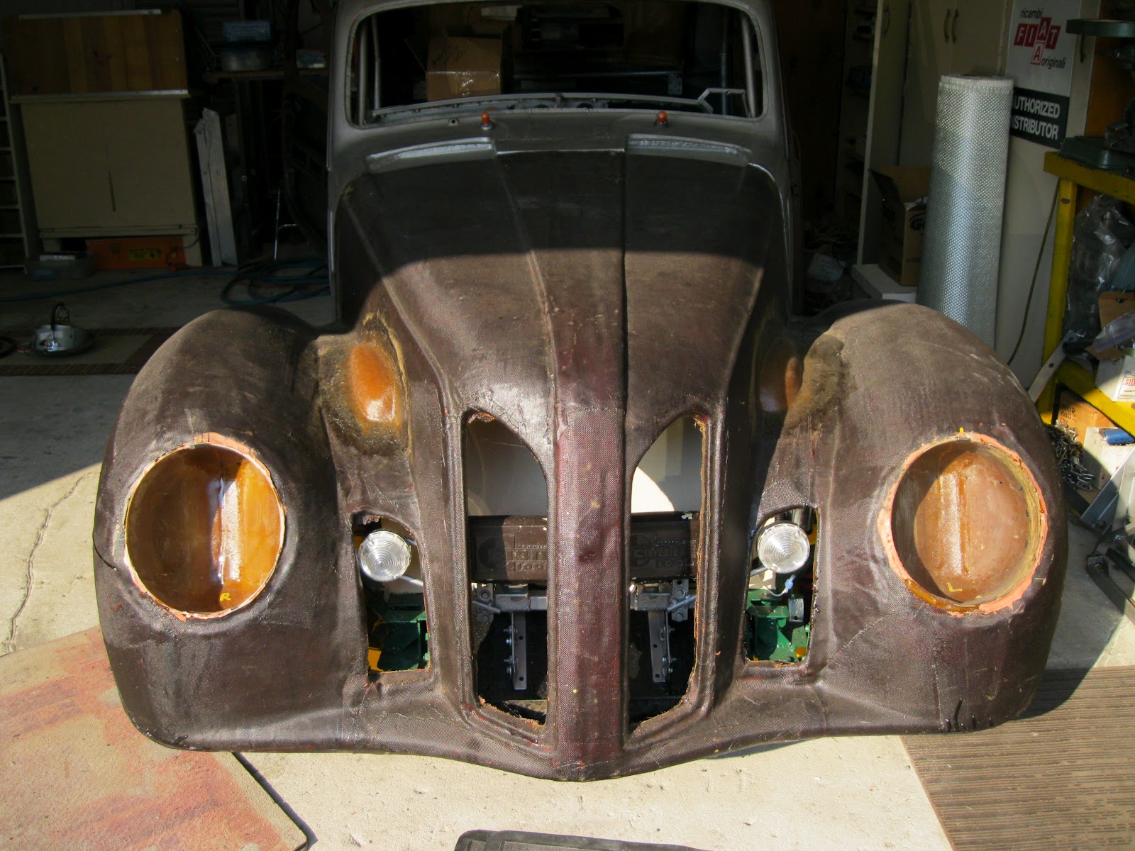
Wednesday, December 5, 2012

VDO CLOCK--MYSTERY

 I need some help here, gang. I received this clock yesterday--for reconditioning--and I have NO IDEA what vehicle it came out of. The owner provided no phone number or email address. Do YOU recognize the critter?The outside diameter of the outer ring is 3.744" and the outer ring is brass color.
 The clock has two mount tabs, as you can see, and the auto-rewind section is the common VDO-Kienzle unit. Build date stamped on the auto-rewind section is 5-73.
Side view of the Mystery Clock. It is a VDO unit so that means it probably came from a European vehicle circa 1973. If you know what it might have come from, please let me know. Jack Ashcraft--phone 541-499-0246  or email me at jacksonashcraft@gmail.com

Sunday, December 2, 2012

BMW MOTORCYCLE IGNITION & LIGHTING SWITCH PLATE

 Holy switchplates, Batman! This is a clear cut case of the good, the bad and the ugly! These are igntion & lighting switch plates from a 72 Bimmer Bike. On the left, the charred remains of the original. On the right, a new switch plate--possibly the only new one in captivity--which set the Bimmer owner back something on the order of $175.00! Yikes!
 View of the BOTTOM of the two plates. Obviously, there is work to be done on Old Nasty [left] which is dead as a door nail here.
 Top view of the two plates. Old Nasty [left] hung in there for 40 years so I reckon the owner can't whine too much about it giving up on him. But it's time to lop off the cremated wires and give the sucker the sheep dip [clock cleaner and rinse] treatment!
HA! There IS life after death! New wires and ready to go for another 40 years! I recondition a TON of switches--for cars and bikes--as well as making auto clocks and cable driven speedometers and tachometers work like new. MOST old dead ones can be revived--good stuff, Mate! 

Saturday, November 17, 2012

BMW MOTORCYCLE--MOTOMETER SPEEDOMETER/TACHOMETER

 Something a bit different.....this is a Motometer speedometer/tachometer from a '72 BMW motorcycle. The Motometer weenies managed to stuff a cable driven speedo AND a cable driven tach into one case. Turns out that the main input shaft housing for both the speedo and the tach are essentially the same, except for different size threads for the drive cables. The item just behind the tach face is the input SHAFT. Just behind it is the input HOUSING.
 This shows the vertical shaft assembly--the gubbins that operates the odometer in the speedo section--which is omitted for the tach. Typical of such 40 year old instruments, the grease was hard as a brick bat. As always, I took the sucker completely apart, cleaned, lubed and adjusted it, and for the speedometer section, calibrated it for speed vs miles.
The whole schmere...well, the major players, anyhow...are shown here. The small cylinders just behind the speedometer assembly are the tubes for four warning lights. Everything in this photo has been reconditioned. All that was left was zinging it back together.  Interesting little instrument!  Don't be hesitant to contact me if you have a cable driven speedo or tach that needs help---I'll take a look at it and see if I can give it some new life!

Saturday, November 3, 2012

SAAB V4 TRANSMISSION DIP STICK

 SAAB, in their infinite wisdom, made the transmission for the 95/96/97 models VERY unhandy when it came to checking the transmission oil level. The drill is to remove the check plug [see drawing above] and if oil runs out, the oil level is good.  If no oil runs out, take out the fill plug and add oil until it does run out, then replace the check plug.  Some Saab owners don't even know where the check plug IS, and has even less inclination to go through this drill.  So a dip stick is a real good idea, and can prove to be a transmission saver since the owner MIGHT actually check the transmission oil level on occasion.
 I built a construction fixture [red item at the bottom in the photo above and top red item in the photo below] that exactly matched an original SAAB trans dip stick, so when the stock of dip sticks have been sold, I whip out the fixture, and make up some more of them.
This photo shows seven [of a dozen] freshly completed dip sticks plus the original Saab dip stick [red, top next to the fixture]. I add the "MIN" and "MAX" notches, as per the original. Now, y'see, all you have to do is remove the fill plug with a 3/8" drive extension, dip the dip stick into the trans, pull it out, read the oil level, add if necessary, put the fill plug back into the transmission case, wipe off the dip stick, and if you're  a neatnick, you didn't even get oil on your hands. PLUS, your transmission stays properly oiled and happy. By the way--SAAB used to offer these dip sticks through their dealers. Since that is no longer an option to the vintage Saab owner, I thought it would be a good idea if I made the little buggers available.  Good stuff, huh?

Thursday, October 25, 2012

Volkswagen Signal Switch Mystery Solved

 This is a 1958 thru 62 Volkswagen direction signal switch--taken apart. These are notable because the switch itself allows both the direction signals and the brake lights to work with just one bulb on each side at the rear. Not this switch though---it worked only part of the time for turning left and not at all turning right.
 I asked several VW techs how this type of switch worked. Summed up, their answer was, "...uhh...it's all in that switch."  I already knew that so I took one apart to find out. Above [left]--the corroded contact plate. On the right-- the greasy mechanical gubbins.  This one was NASTY inside!   
 The same grubby contact plate on the left. On the right--an interesting rotating contact plate that makes the one-bulb system work correctly.
 The parts look a lot better after going through the sheep dip in the ultrasound tank. I gave the parts a special rinse in the ultrasound tank and careful lubrication with modern, non-hardening lubes. Nothing was broken in this switch--but it was a mess of old, very hard grease and a lot of corrosion.  
All better now and ready for another 50 years of service in somebody's restored Beetle!

Thursday, September 27, 2012

SONETT II & SONETT V4 REPLACEMENT IGITION SWITCH

Ignition switches get tired after being twisted for over 40 years. Sonett II and Sonett V4 cars at least have an ignition switch you can replace without dismantling the steering column assembly, which is the case with a Saab 95 or 96. The problem with all these cars is that Saab saw fit to run four or five circuits with current that had to pass through the ignition switch.  NOT one of their better ideas.

Finding a replacement switch that will mount through the plywood instrument panel was tough enough. Finding one that looked "original"--with keys that say "SAAB"--just wasn't gonna happen--so I figured--just get over it. My solution is shown. The 40 amp relay [extreme left in the photo] keeps the electrical circuit load off the switch and the whole assembly just plugs into the wires that were originally connected to the ignition switch. I matched the new wire COLORS to the old wires and also marked each wire with bands. One hole has to be drilled to mount the relay [I know that's a toughie], but the rest is pretty much "plug and play".  As a last resort sort of thing, I put together illustrated step by step instructions. See--I hate to recreate the wheel every time I do something.

SAAB LIGHTS IN AN ITALIAN CAR ???

 This conglomeration of wires and "stuff" will be one of several interior lights in MR T, my 1937 FIAT Topolino "EuroRod". If you guessed that the two lights were Saab 99 interior lights mounted behind the inside rear view mirror---you're right!  The piece of steel angle [on the right, above] will mount the lights just under the rear window on MR T, to light the luggage area behind the seats.
Here is the assembly, ready to install. I'm in the process of doing a complete, NEW wiring job of the entire car, using a LOT of plug-together connectors like the one at the extreme left of the photo above. All good stuff....for someone who actually LIKES to do automotive wiring! 

ITALIAN CLOCKS IN A SAAB ???

 Here are the gubbins of a couple of ALL ELECTRIC clocks from a couple of Saab 96's. The dial indicator gives you an idea of the size of all that stuff that makes up tickerator. [Good word, eh?]
 These all-electric Italian VEGLIA clocks do NOT have the auto-rewind package used in a lot of the VDO tickerators. Instead they have a coil [see photo below] that starts the rocking action of a small weighted wheel that puts the gearset into motion, causing the hands to move. 
 The small "spoon" [just above the coil] is an electrical connector. As with ALL clocks, these little suckers have to be carefully cleaned, rinsed and then lubed with professional "right stuff", or there's no point in trying to recondition the clock in the first place. I also "hot check" 'em for an hour, to check for time accuracy and to give them a fresh run-in period after they've been messed with.
Here is a reconditioned tickerator. There are four parts missing: a chrome "cup" that fits over the set shaft next to the glass, a wee spring, a chrome set knob, and the setscrew that holds the knob in place. They were not on the clock when I received it from the customer. I hope he held on to them because they are made of "unobtainium."

Thursday, August 30, 2012

TOPOLINO HEADLIGHTS & WIRING

 Say hello to "MR T..."   I got tired of looking at empty light sockets and wired up the VW Beetle headlamp assemblies to go into the wee car. I had already installed the signal lamps in the small grille openings on each side.
 Here's the wired up light set. Beetles had the park lamps inside the glass in these headlight units.  Works OK for me---Hey! It's a 1937 car!
Even boids flyin' over think MR T looks better with his eyeballs installed!

SAAB 95/96 IGNITION KEY/SWITCH/RELAY SYSTEM

This conglomeration of wires and stuff is [left to right] 1--the steering column housing from a Saab 95/96. You are looking at it from a view you will never see when it is mounted inside the car. The steering wheel would be just beyond the TOP of the black housing. The round shiny thingy at the right center is a new, heavy-duty replacement ignition switch.  It is part of one of my new ignition key/relay systems for these cars. The relay is under the switch on the outside of the column housing.  The wire bundle is routed to plug right back into the original wires that were formerly attached to the stock ignition switch.
2--Center is the assembly jig showing the same switch, relay and wiring bundle.
3--At right is a completed system, ready to go in the box for shipment to a Saab customer who really would like to just get into his car, shove in the key, turn it, start the engine and be about his business. 

These are the same items, viewed from the front. Note that the ignition key is now on the LEFT side of the column housing. SOME 95/96 cars had the 4-way flasher switch on the left. It is now on the RIGHT, for those cars. MOST 95/96's had the 4-way switch up on the panel to the left of the instruments, AND For those cars, there is a black, push-in plug that covers the ignition key hole on the right. It's a neat, bullet-proof system!

Wednesday, August 15, 2012

SAAB Sonett III New Ignition Switch System--Testing

Old--uhh--VINTAGE--cars tend to wear out. Or break stuff. On vintage Saabs the ignition keys/cylinders/locks get tired and finally head West. New Saab parts are NOT available, so I engineer good quality replacements that work well and are reliable. In the case of the Sonett III cars, you have it easy. All you have to do is get rid of the housing that carries the key cylinder AND the steering column lock mechanism. It is a pain in the butt anyhow. Saab 96 & 96 cars are even worse, but I'll talk about them later.

 Saab used snap off bolts to hold the mechanism to the  Sonett III steering column. I use a very sharp small chisel and ball peen hammer and back those bolts out. It is easier than you think [see drawing above]. I have a very good replacement system for the Sonett III cars, which bolts quickly back into place, right where the original assembly sat.
 I refuse to install anything I don't test first. Above is the simple test rig I use to make sure I have the replacement ignition switch system wired correctly. The bulbs light up as I turn the new switch to it's "ON" and "START" positions.
 The switch is in the "ON" position here. Current is flowing through the heavy wire that will feed 5 fused circuits in the Sonett, as well as to the coil circuit for running the engine. I got that one wired correctly--HA!
This is the prototype replacement switch/relay/wiring/mount  assembly for a Sonett III. It would be rotated 180 degrees to mount in an actual car. Once in place, all you have to do is pull the wires off the old ignition switch--one at a time--and plug 'em into the [well marked] wires shown here, and you are good to go. Pretty neat, eh?

Wednesday, August 8, 2012

Engine Cooling Fan Fix

Everyone needs to work on his/her Subaru Brat once in a while....assuming he/she owns a Subaru Brat. This is "MR B", my wee Subie 2 or 4 WD pickup. Neat little truck!

 MR B has two electric engine cooling fans. The No. 2 fan decided to SQUEAL at me a day or so ago. So I got the battery out of the way, and with only minor amounts of swearing, pulled the fan assembly.   
 These are the parts---fan blade, motor ass'y and mounting shroud.
 The sealed motor is NOT meant to be taken apart. So, of course, I took it apart. The shaft bushings--after only 182,000 miles--were dry. I cleaned up the armature, the shaft, the bushings and the four wee brushes, lubed the bushings and put it back together again. Works like a champ.
The assembly, ready to go back into MR B.  Good to go for another 182,000 miles. See how much fun it is to work on your Subaru!

Sunday, July 15, 2012

TOPOLINO HEATER/DEFROSTER CONTROL BOX

MR T, my 1937 Fiat Topolino EuroRod, got a bit more attention during the last week. Above is the custom heater/defroster control panel that I built. The car is very small so I've attempted to make every part in the car do two or more jobs. This panel is no exception. The knob on the left controls heater fan speeds, the slides just to the right
control heat, vent and defrost on the heater "box" itself. The center orange lamp indicates when the secondary direction signal semaphores pop out and flash. The red lamp just below lights up when the emergency brake is "on". The two slides on the right control the outer air inlet door on the side of the cowl ahead of the right door, and the 3 position switch on the right controls the semaphore flashers on each side of the car.

 This shows the INSIDE of the panel and all the gubbins that go into, or onto, it. The flasher units [top right] are for 1] the regular direction signals, and 2] the semaphore flashers.  The latter are just for fun, but they were standard equipment in 1937. 
 This is the inside with all the bits mounted up. Two relays are mounted outside the box [extreme left side].The unit under the box on the left is the intermittent windshield wiper switch [a standard item on '70's-'80's Fiats], and the two flasher units are under the box on the right. It will get a lot more interesting when all the wires are added, plus the five operating cables. Like I said, I like to make one item do a lot of jobs, and this is typical of the whole car.
For some reason the front surface looks grainy in this photo. It isn't--it's smooth. The box is 10.5" wide and 2.75" high.  My wife says I'm having WAY too much fun with this little car. I just look at her and grin and say, "Yeah--ain't it great?" 

Wednesday, July 11, 2012

SAAB RIBBON SPEEDOMETER REBUILD

This is a "ribbon" speedometer from a model 93 or early 96 Saab. The photo below shows how the poor thing looked when I took it apart---YUK! After I took it completely apart, blew the spiders out, cleaned out the rust and general crud, it began to look a whole lot better.

 The unit has five main parts--the cast aluminum face [top], the clear plastic "glass" [behind the face], the sheet metal number panel, the cast aluminum back case, and the speedometer gubbins themselves [shown here inside the back case].


 I went through several cups of coffee getting the speed drum out and cleaned up. I had to "unfreeze" the input housing with the magnet and the primary odometer drive [extreme right, at top]. The geartrain leading to the odometer wheels was a mess, as usual, and looked like they had been underwater for a few years [they are all cleaned up here, ready to go back in the case and be properly lubed and adjusted].


I painted the case--inside and out--and polished out the badly scratched plastic "glass".  You can see that the odometer is reset to all zeros plus point four miles--the last number wheel is for tenths of a mile. I even replaced the colored  plastic for the indicator lights--seems like those litle buggers are always shot. The small one right under "SAAB" is red, the larger one below that is green. So this remnant of Saab antiquity looks and works like new once again--it's ready for another 50 years of faithful speed-O-ing.  Old Trolls are like that.

Saturday, June 30, 2012

FIAT TOPOLINO----HEATER CORE CHECK


Now for a change of pace!   The top photo is my 1937...yup THIRTY-seven...FIAT Topolino ["Little Mouse"] "EuroRod".  The running gear is almost all 1980 Fiat 124 Spider--2-litre twin cam engine, 5 speed transmission, 4-wheel disc brakes, tilt wheel, and more. Saab parts include a Sonett steering rack, a 900 Turbo aluminum radiator and 99 rear suspension trailing links. Sonett coil springs are fitted on all 4 corners.

The hood/front fenders ass'y is all new fiberglass [and tilts forward as a unit] as are the rear fenders [which do NOT have wheel cut-outs]. The rear fenders are removed by taking out one bolt. The fiberglass center roof section is removed by unsnapping four convertible top over-center clamps.

The heater assembly was pirated from a Fiat 124 Special Sedan. I thought it might be wise to check the heater core and heat control valve for leaks--OUT of the car. This is  the test set-up, using a cooling system pressure tester.

The valve--top left on the core--leakd, so I replaced it. The pressure gauge has 13 psi on it, a pressure that held for 30 minutes. Good to go. One more block checked off.
Oh!  Yes, those ARE suicide doors!

Friday, June 29, 2012

SPECIAL SPEEDOMETER TOOLS--VW

So far in the speedometer reconditioning adventure, I've built close to 50 special tools. Each VDO speedo is enough different that new tools have to be figured out and built as the job progresses.  This is a VW late Beetle [not the NEW Beetle] speedo with the tools required to do the internal reconditioning of the bugger.  There are some more special tools to get the outer chrome ring, glass and inner ring off [these parts are shown laying behind the speedo unit in the photo].

Ahhh...but the formerly grimey, ugly, siezed-up speedo looks and works so GOOD when I'm done with it!