skip to main |
skip to sidebar
These are NOT fiberglass bolt bins, though they ARE fiberglass. Each, except for the dark one in the center right, is the main body of a cover for a glass hatch latch, for a Saab Sonett III. The dark one is the steel mould for these things that I built about 25 years ago. The ten bodies shown have been popped out of the mould and trimmed, at this point.
Here is another view of the ten latch bodies [I believe in mass production, y'see...] and the steel mould. Each latch body has 8 plies of 8 ounce fiberglass cloth. The resin matrix is polyester. You know---that stinky boat resin stuff.
You can see that I have added a flat fiberglass plate on what will be the TOP surface of each cover. I pre-drilled the holes in the plates before bonding them to the main cover bodies. The rusty colored "thing" at the bottom is an original, factory plastic latch cover. The sun warps the plastic, makes it brittle and most of them found on Sonett III cars these days are complete junk.
Three further stages of assembly are shown here. On the left, the cover with plastic filler completely sanded, ready for paint. In the center, a cover in primer, wet sanded and ready for color. On the right a cover painted and ready for installation in a Sonett III. There is a whole LOT of hand labor making these things look this good. Sand, fill, sand, fill, swear, sand, swear, fill, swear....
Another view of the last three stages. I supply new stainless steel 1/4-20 bolts and stainless washers with these completed latch covers. These critters won't warp or get brittle--they'll probably outlast the rest of the car. Pretty neat, eh?
This is a study in contrasts. In a vertical row on the left, parts of a British Smith's tachometer. The vertical row on the right shows the similar parts of a U.S. Stewart-Warner tachometer. Both are cable driven. The Smith's unit used what was called a "chronometric" internal mechanism to motivate the needle around the dial. The S-W unit used a common, and very simple, rotating magnet to move the needle. The Smith's tach was built around 1950, before the Brits had discovered magnetism, I think; the S-W unit around 1960.

You want contrasts, here's more. The Smith's tach [left] has a brass face and cast aluminum frame. The S-W tach a thin steel face and plastic frame. But the BIG contrast is in the internal gubbins. Just look at all that "stuff" in the Smith's unit. Levers and gears and balance arms and a couple of crude camshafts, and some other items identifiable only if you live in the outskirts of Coventry, England. The S-W uses, simply, a rotating magnet in sort of a modified half cup shape that rotates around the round "can" that is connected to the speed needle.
There was at least SOME justification for Smith's use of the monkey-motion mechanism. First they used the chronometric jazz in their speedometers. If you look closely at the frame of the Smith's unit you will see holes in the legs of the frame where--if this were used in a speedometer--the odometer registers would be fitted. Take out the odometer gubbins and Presto! Instant tachometer! Clever, aye, mate?
Well....yes and no. There is this thing called complexity. Murphy's law says that the more "stuff" in a unit, the more apt the unit is to screw up. When I received the Smith's tach, the needle would go to maybe 15 [x100] rpm and stop. It looked like it had been Arabia with Sir Lawrence [who wasn't a "Sir" then] and needed TWO baths in the ultrasonic unit with clock cleaning fluid. Then a rinse, then careful oiling with clock oil. I didn't have high hopes for the sucker.
But I put it on the test bed and started the [anti-clockwise] rotation and th' blinkin' blighter started working! Chronometric tachs sort of step up, in about 500 rpm jerks. This one settled down at 6800 rpm, steady as a Spitfire in a dive after an ME-109. When the input rpm is slowed to a stop, the chrono tach backs down in about 2500 rpm steps.
Amazing what can happen when you get 65 years of dirt, dust and sand out of all of the monkey-motion bits in one of these critters.
But I look forward to peering into the bowels of a Smith's tach after they discovered magnetism....that happened in about 1990, if memory serves me correctly....
Believe it or not, what you see above are instruments from a 1950 VW Beetle. I received these beat-up buggers from a customer with a plea to make 'em "like new." On the left, two speedometers, on the right a wind-up clock. In the center, two "pods", as VW folks call them, that hold the speedo and clock and then bolt into appropriately sized holes in the instrument panel.
This is the flip side of one speedo, the clock and the pods. Note that the speedo pod also mounts the ignition switch, and switches for lights and windshield wipers. As you can see, 65 years allows pleanty of time for crud to build up on all the bits.
Both pods are cast in bakelite, as far as I can tell. Four idiot light mounts are also cast into the pod. There was quite a bit of brass--for wire connections, etc--to be polished up, and the switches had to be disassembled and cleaned, then reassembled--in the correct order and orientation. The bits only go [correctly] together one way.
The clock--cleaned up and ticking--in its cleaned, primed and painted pod. The shaft at the bottom combines to wind and set the time of the ol' ticker. The new rubber seal [black in the photo] around the pod cushions the unit in the panel.
Here are the pair, ready to go to the owner. Note the switch knobs--very much 1950's style--on the speedo pod. These are to go into a completely restored Beetle, and will probably be the highlight of the interior of the wee bug. They led me a merry chase, but I'm quite pleased with the final result. Good stuff...
Every V4 Saab owner's dream: A hot dog V4 engine with the legendary cross-ram intake manifold and a pair of Weber DCOE carburetors---WOW! This is one of two such engines that I built for a pair of Peking to Paris Saab 96 rally cars some years back. Note the special distributor, necessary to clear the intake runner for the right carburetor. Most, if not all, of these special intake manifolds were made up in England for Saab in enough quantity for Saab to qualify for homologation according to international rally competition rules. The manifold set you see here is the "factory" set-up.

There were several "wannabe" intake manifold builders so if you run into a cross-ram set-up it may or may not be what you see in the top photo. Each wannabe also made up some sort of distributor extension. In this photo, the distributor on the left is the Bosch unit made specifically for Saab for the rally cars. The distributor in the middle has an extension that uses a standard distributor. The distributor on the right is a stock unit, though the drive gear at the bottom has not been installed.
Here is a good look at the Bosch distributor made up for Saab. You can see that the distributor body and the extended shaft housing are all cast in one unit.
This is a third distributor for a cross-ram manifold set. The housing extension is different [shorter] than the one shown above. I just rebuilt this distributor for a customer. The add-on housing looks OK in the photo but is actually really crude and looks like it was done by two guys under a pepper tree with a hammer, hack saw and bastard file after the second six-pack of Bud....
The reconditioning of the distributor was straightforward, and I made the extension work, but a much better extension should be machined from a bar of good quality aluminum. I have made up machine drawings for just such an extension.
Does the vacuum advance unit look different? It's a much modified Hitachi with a special adaptor mount. I get the exact advance curve I want with this unit, but it is NOT "Plug & Play", with MUCH testing on the SUN distributor machine to be sure I have the correct modifications to get the right advance curve.
It is important to understand that advance curves--both mechanical and vacuum--must be tailored to the way a given engine will be USED; the goal being to promote performance while preventing pre-ignition [detonation] that can destroy an engine. Fun stuff, but as they say in the ads, "Don't try this at home..."
 This is the classic "Before and After".....the top photo is the before, as you might suspect. It is a square body Lucas windshield wiper motor out of a '68 Saab 96V4, just as it looked when I took the sucker apart---YUK! This one had more GREASE--old, nasty, hardened crap--in it than any wiper motor I've ever worked on before. The owner said it only worked on one speed, sometimes. Given the amount of nasty gook inside it is a pure wonder that it worked, ANYTIME! I suspect that some "wrench", at some time, figured that "if a little does a little good, a LOT has to do a lot of good", and applied grease by the handful....
The second photo shows the same unit--cleaned and ready for reassembly, adjustment and testing. There were NO bad parts, just greasy parts, in this one. Even the armature and contact brushes were quite good.
This shows the wiper motor on my test bed. The different switches, and the relay that you can see duplicate the wiring for ANY Lucas wiper motor that I rebuild. This one passed all the tests with flying colors.
Isn't that one pretty! Ready to go to the customer, LOOKING, and WORKING like a new one. Good Stuff.
This is the classic "Before and After".....the top photo is the before, as you might suspect. It is a square body Lucas windshield wiper motor out of a '68 Saab 96V4, just as it looked when I took the sucker apart---YUK! This one had more GREASE--old, nasty, hardened crap--in it than any wiper motor I've ever worked on before. The owner said it only worked on one speed, sometimes. Given the amount of nasty gook inside it is a pure wonder that it worked, ANYTIME! I suspect that some "wrench", at some time, figured that "if a little does a little good, a LOT has to do a lot of good", and applied grease by the handful....
The second photo shows the same unit--cleaned and ready for reassembly, adjustment and testing. There were NO bad parts, just greasy parts, in this one. Even the armature and contact brushes were quite good.
This shows the wiper motor on my test bed. The different switches, and the relay that you can see duplicate the wiring for ANY Lucas wiper motor that I rebuild. This one passed all the tests with flying colors.
Isn't that one pretty! Ready to go to the customer, LOOKING, and WORKING like a new one. Good Stuff.
Time for more fiberglass fun on MR T, my 1937 FIAT Topolino Cabrio....In this photo I have the back fenders mounted [and each held in place by two bolts] and the valence between the fenders at bumper level in place. Now it's time to build the spare tire cover. If you look closely you can see a fiberglass ring around the spare tire, right at the body surface. I laid up the ring first to get a nice "fit" to the body of the car, which is really a compound curve in that area.
I attached a 0.375" center pin to a mounting structure that will hold the pin exactly centered and vertical. You can see the mounting structure attached to the ring. The shaped board [light color, top right] can spin around and will cut the foam [see next photos] to get an even shape for the spare tire cover.
I used urethane foam [of the type used in constructing composite aircraft] to make the basic form of the cover. Here the foam--mounted to the ring--is ready for carving to the final shape of the cover. [You can see MR T behind the table].
There is always some rough--but careful--cutting to be done before the spin cutter is used. That's what I'm doing in this photo, using a "Sureform" rough file for the job. The action here is to rough file a pit, then check it with the spin, which you can see mounted to the center pin in the photo above. The spin arm makes the final, fine cut of the foam.
The foam shape is done. The check template shows a good "fit", all around what is essentially a male mould for the cover. Time to lay on fiberglass cloth now.
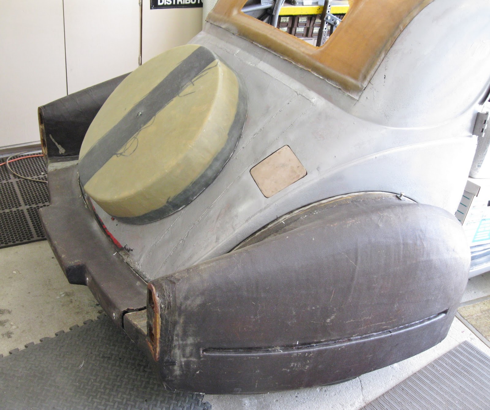
AHA! It's laid up! I laid on seven plies of aircraft bi-directional cloth, directly to the foam mould. Five plies are of 8-ounce cloth, the final two plies are 4-ounce cloth. The dark band is of 8-ounce bi-directional GRAPHITE cloth, to give extra strength on one side for the hinge, and opposite, the latch. You can see a band of graphite around the base, at the junction of the new cloth and the original 'glass ring. I give the lay-up a minimum of 24 hours to complete the cure of the aircraft epoxy that I used. I used NO polyester resin on ANY part I made up for this car. Epoxy resin makes a lay-up at least twice as strong compared to using polyester resin. Two further benefits: This particular epoxy has almost no odor, and the working time is easily 20 minutes.

The new cover is cured, trimmed and setting in place on MR T. The fun stuff now is to mount the hinge [which will be centered on the LEFT] and build and install the latch mechanism [which will be centered on the RIGHT]. More on that in further adventures with MR T....
It seems Sonett III owners all over the place have either lost their ignition keys, never had ignition keys, or the ignition switch finally packed it in. These are the parts to make up four changeover ignition switch kits for those cars, and will be shipped out to owners whose wives have told them to "...get that damn can running or get rid of it!"
At the top of the photo are the mounts. Below that the switches and relays and finally, the connecting wires. Each wire has an identifying tag to make it easy for the owner to install the kit.
Here is an assembled kit, viewed from the back. The switch is on the left. Next to it a 50 amp relay. In this photo, the wires have not yet been collected into a small bundle to "neaten things up".
Here is the front. The unit mounts right where the original Sonett III ignition assembly was mounted. Once installed, you have to look closely to see that it is not the original. I include step by step instructions. All the wires are clearly marked to correspond to the wires you pull off the back of the old switch. This is about as close as you can get to "plug and play".
Best of all, you get to keep both your Sonett AND your wife!
SAAB V4 clutch problems are very often made worse by a worn clutch release arm. The drawing above shows the location of the release arm in the transmission bell housing, then [above and left] the release arm itself, and finally, above that, the fat arrow shows how the release arm gets worn where it holds the release bearing peg. These release arms are, of course, no longer available new, so the solution is to rebuild the arm by partially welding up the hole at the top and the "C" cup at the bottom, then machining them both out to fit the new release bearing.
This nasty bugger is how most of 'em look when I get 'em. It's hard to see in this photo but the welding has been done. I have a special jig I use to get the hole and the cup machined back out to the correct size and location [relative to the center line of the
main "pipe" [on the left]. The clevis [top] and its pivot pin also get badly worn.
I drill out the clevis rod [top] and the holes in the loop of the arm and use an oversize pin to eliminate the slop in that part of the arm. This is the reconditioned release arm, with all the related parts, including the new release bearing and retaining clips. Good as new and a lot prettier...heh heh heh.
The drawing shows the shift linkage for a Sonett III, from the shift tower [on the left] to the transmission [on the right]. Both the shift tower and the linkage support [bolted to the transmission] have two bronze bushings [see arrows]. Saab must have managed a "real deal" on the bushings because they get sloppy after only a few jillion shifts, and that, along with the fact that Saab did not add spring in the linkage to load the shifter to the 3rd-4th gate, can make selecting the correct gear a bit of a crap shoot.
These are the parts for the linkage at the transmission. But first, one other comment: The actual movement--INSIDE THE TRANSMISSION--from neutral to say, 3rd gear, is only about 1/2 inch [13mm] or so. So it doesn't take much slop in the linkage to confuse gear selection. That's why bushing wear can make things sticky-wicket in the shifting department.
Above--the support fixture with all the bolt holes has a bushing in each end. These are the ones that have to be replaced. Problem is, correct SIZE bushings are not available.
I get bushings that are just larger than the originals, chuck 'em in the lathe, and carefully machine them until they are just about 0.002" larger outside diameter than the inside diameter of the support housing. Then I press them into the housing. Above is my lathe setup for machining the new bushings.
Here is a photo of the old bushings and the support housing with the new bushings installed. Note that once I press the new bushings into the housing I still have to ream the INSIDE of each bushing to shaft size plus 0.002". Note that I also drill and tap the housing for a grease zerk so the bushings can actually be lubricated. [THAT is a novel idea the Saab engineers never thought of, apparently....]
This is the finished product, ready to go into the car. Might last a few jillion more shifts, especially if it gets a squirt of grease now and again...
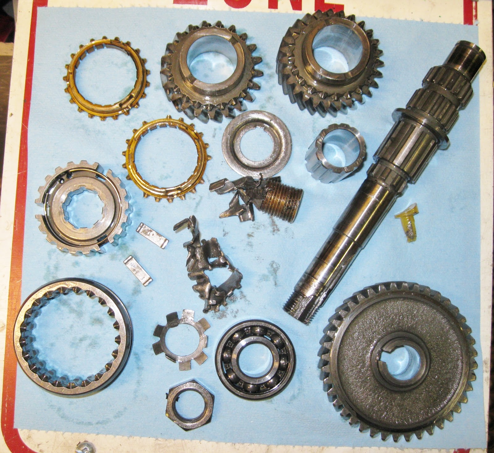
These are a few of the buggered up transmission parts that I found in the bottom of a transmission I just rebuilt for a customer. This was strange because I usually don't find this sort of damage. It was also strange because the transmission was CLEAN inside. Clearly, someone had been into it recently and had screwed up the job. Also--parts were missing and every case bolt was WAY too tight, as if it had been put together using an impact wrench, which is NOT a good idea. ALL the bolts/nuts in these Saab transaxles must be torqued to the specs provided by Saab in their factory service manual.

Once I had the bell housing off, it was clear what had happened. The nut at the end of the countershaft [shown] had come loose. The shaft then "floated" and the result was that every part shown--3 gears, the shaft, low and second synchronizer rings, the synchronizer hub and a bunch of smaller parts--were all busted up and had to be replaced. All because the moron who was into the transmission last did not correctly torque the nut at the end of the countershaft. OY!
Well, here is the reassembled gearbox. All countershaft-related damaged parts--as well as others damaged because of the countershaft problem--have been replaced. Note that the 'box is in my factory transmission jig. Using this jig--and the 20-odd factory tools that go with it--is the ONLY way to be sure that an overhaul of one of these transaxles is done correctly.
There are a number of internal adjustments that MUST be done correctly--some with correct thickness shims, some with feeler gauges, and this one with a dial indicator set up--to insure long life and reliability of the transaxle.
Here is the finished transaxle. I always specify the use of synthetic transmission oil--AMSOIL being the BEST, in my opinion--so I use an anerobic sealer, which is not attacked by synthetic oils--for all case mating surfaces, and on both sides of the rear cover and top cover gaskets.
Another view of the completed transaxle. Note that there is NO freewheel control lever. This unit has been "neutered" so the freewheel--a carry-over from two-stroke engine days--does not function. It is very easy for the V4 engine--which actualy has TORQUE [compared to the two stroke] to damage the freewheel unit. It is worth noting that I DO NOT weld internal parts to neuter the freewheel! At any time in the future, the freewheel system COULD--if the owner got soft in the head--be put back into use.
Call it "Murph'y Law" or BumLuck or any other saying regarding mechanical difficulties, but recently I have encountered not one, but TWO problems with V4 Ford/Saab cylinder heads for high performance engines.
Take a look at my exploded view drawing above. Note the exhaust valve hard valve SEAT. Today's unleaded fuel will cause early exhaust valve failure without hardened exhaust valves and valve seats. So far so good...
I install larger diameter valves and of course larger exhaust valve hard seats. I've rebuilt dozens of V4 engines with these big valve cylinder heads, with no problems. Still, so far so good.
A couple of weeks ago, my machinist found a "pocket"--a casting flaw--in a cylinder head, where he had machined the head to accept a larger diameter hard valve seat. Result? the head was instant junk. Kauput.
This week, another bad cylinder head....
This head [shown above, before installation] was on an engine installed in a customer's Sonett III, and I discovered--during the 500 mile drive-off--that the right side exhaust pipe was putting out WHITE smoke. Not a lot at first, but it got worse as the end of the 500 miles approached, it was obvious that it was not going to get better. A compression check showed equal compression in all four cylinders and a vacuum gauge check showed steady--and correct--manifold vacuum for this elevation [1350 feet above sea level].
I retorque the cylinder heads and intake manifold to factory spec's 3 times during the 500 mile drive-off runs. The drive-off period allow correction of [usually] small glitches that always appear--in any number of areas--when a car has undergone a full restoration.
I removed the carburetor, intake manifold and right hand cylinder head. Close examination of the head and intake manifold gaskets showed no damage to either, but it was clear that there was a big problem in the forward [No. 1] combustion chamber. The exhaust valve was VERY white, indicating a lot of heat, and there was a bit of fluid around the intake valve. I had certainly found the area of the problem.
NOTE: White smoke in the exhaust means coolant is being sucked into the combustion chamber. Blue smoke means OIL is being sucked into the combustion chamber, either past the valve guides or past the piston rings, or both. Black smoke means the engine carburetion is WAY too RICH. Smoke of ANY kind from the exhaust means further investigation is needed, and soon.
The reason for the problem was a crack in the cylinder head at the intake valve seat, where apparently the machining of the head to accept a larger valve had either come close to another pocket in the head casting, or was simply because after machining, the wall thickness between the seat area and the water jacket was thin enough that it cracked with the heat of combustion. NOTE: both head were magnefluxed after machining and showed NO cracks.
Well...shit happens. Particularly when you are trying to get a quart's worth of work out of, essentially, a pint pot. My modified V4 engines produce 115 to 140 horsepower, depending on how thick the customer's wallet is, but the more power you produce
the more possible are the unexpected results. Usually....everything is just fine and the customer gets a really nice engine that will be as reliable as a factory engine.
But sometimes...shit happens. That's why we ALWAYS do a 500 mile drive-off before we deliver a restored Saab to it's owner, and why we insist that the owner of one of our reconditioned V4 engines follow the instructions we include with the engine when we ship it to him.