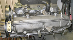
Here is a FIAT twin cam cylinder head, from a 2-litre [1995cc] carbureted engine. The owner wanted more performance, so in addition to adding a Weber 32/36 DGV-5A carburetor and a set of headers and better exhaust, I put in a set of camshafts from an earlier, 1438cc FIAT twin cam engine. They are an exact interchange, BUT the earlier cams have more lift and will give a big bump in the horsepower curve.
The valves, when pushed open, extend below the level of the cylinder head so a holding jig is necessary to avoid bending one or more valves in the process of doing the camshaft interchange and subsequent valve adjustment. I built this one some years back and it will support several different types of cylinder heads, even a GEO Metro head. [GEO metro....?]
Here are the exhaust camshafts for both engines. Note that the 2-litre cam has big, lazy lobes. You can't see it in the photo but the lift and duration are different between the two camshafts. The cam followers are all in a row at the top of the picture. The actual valve adjustment shims fit in the TOP of each of the followers, not inside.
This shows the exhaust camshaft housing, with the cam and drive gear for the notched belt in place. At this point the housing with the cam followers [not installed here] is ready to be installed on the head.
I build a lot of special tools. The stud with the screwdriver slot in it is one of two. They serve to hold the cam housing-to-head gasket in place and as a guide while I set the cam housing onto the head. All the bolt holes line up--no fudging around. Neat.
Now the fun begins--getting in the correct shims to give proper valve clearance. The tools are FIAT items. Here is how they work: With the camshaft turned so the lobe is angled up, away from the lifter, you use a feeler gauge and measure the clearance [between the camshaft and the follower]. Spec for exhaust valves is 0.018" to 0.021"--I like to set them at 0.020". If you do not have the correct clearance, you push the spade ended black handled gizzmo in between the camshaft and the hardened shim, which is sitting on top of the cam follower "bucket". Then you rotate the little tool [which I have in my hand] around the cam and situate it so its fingers sit on each side of the "bucket". Then you use a shot of compressed air and the shim will pop out of its place on the top of the "bucket".
Measure the thickness of the shim. I use the micrometer to check that my digital caliper is reading accurately today. If the clearance is too tight, you install a thinner shim. Then remove the tool and recheck the clearance. Repeat as required. [Note--spec for the INTAKE valves is 0.015" to 0.019"--I set them at 0.018"].
Note the cam followers ["buckets"] next to the digital caliper. Four of the followers are turned "right side up". Two of them have shims set on them so you can see where the shims fit into the recessed area at the top of the follower.
It is nice to have a full set of shims, separated by thickness sizes.
And here's the finished head, ready to set on the engine. If YOU are doing this, some things to remember: The camshafts MUST be in the correct position, the engine timing mark on the front pulley MUST be on Zero, and you MUST use a NEW timing belt. It is also a really good idea to install a NEW belt tensioner--the bearings in the old one are probably shot. READ THE SERVICE MANUAL!


No comments:
Post a Comment
Note: Only a member of this blog may post a comment.